Archive for the ‘Recover Chip’ Category
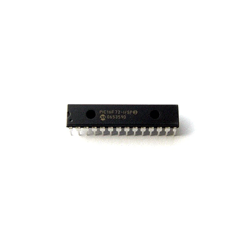
 Recover MCU PIC16F72 Code
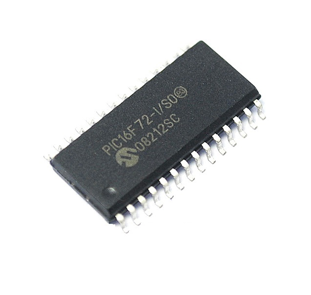
The PIC16F72 microcontroller stands as a cornerstone of embedded engineering, widely deployed across automotive control modules, consumer appliances, industrial automation, and smart medical devices. Known for its cost-effective architecture, integrated analog-to-digital converters, and highly reliable flash execution, this chip frequently acts as the primary brain harboring critical operating firmware. For organizations aiming to repair legacy systems, maintain long-term infrastructure, or conduct legitimate interoperability analysis, accessing the compiled software dentro these units is vital. However, because these systems are routinely deployed with their security mechanisms fully active, engineers frequently encounter a locked or protective environment designed to prevent direct readout of the internal eeprom and flash memory data.
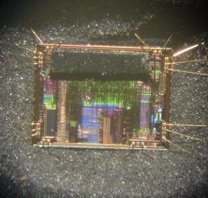
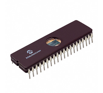
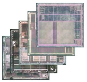
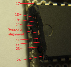
When organizations face a bricked system or a legacy hardware bottleneck without original documentation, our professional services provide a safe, reliable path to retrieve the binary payload. We specialize in advanced hardware analysis to safely bypass the secured or encrypted flags on the chip, enabling clients to recover MCU PIC16F72 code seamlessly. The technical process requires deep expertise in physical and electrical domain methodologies. Engineers safely break the exterior molding using specialized techniques to decapsulate the chip, exposing the raw silicon die structure under microscopic instrumentation. From there, micro-probing or controlled environmental adjustments are utilized to decode the state of the configuration registers, allowing us to attack the hardware boundaries safely without destroying the underlying architecture. This allows a technician to successfully hack past the embedded security bits to extract the pristine heximal program file.
High Performance RISC CPU:
· Only 35 single word instructions to learn
· All single cycle instructions except for program branches, which are two-cycle
· Operating speed: DC – 20 MHz clock input DC – 200 ns instruction cycle
· 2K x 14 words of Program Memory, 128 x 8 bytes of Data Memory (RAM)
· Pinout compatible to PIC16C72/72A and PIC16F872
· Interrupt capability
· Eight-level deep hardware stack
· Direct, Indirect and Relative Addressing modes
Peripheral Features:
· High Sink/Source Current: 25 mA
· Timer0: 8-bit timer/counter with 8-bit prescaler
· Timer1: 16-bit timer/counter with prescaler, can be incremented during SLEEP via external crystal/clock
· Timer2: 8-bit timer/counter with 8-bit period register, prescaler and postscaler
· Capture, Compare, PWM (CCP) module
– Capture is 16-bit, max. resolution is 12.5 ns
– Compare is 16-bit, max. resolution is 200 ns
– PWM max. resolution is 10-bit
· 8-bit, 5-channel analog-to-digital converter
· Synchronous Serial Port (SSP) with SPI™ (Master/Slave) and I2C™ (Slave)
· Brown-out detection circuitry for Brown-out Reset (BOR)
CMOS Technology:
Low power, high speed CMOS FLASH technology
Wide operating voltage range: 2.0V to 5.5V
Industrial temperature range
Low power consumption:
Special Microcontroller Features:
· 1,000 erase/write cycle FLASH program memory typical
· Power-on Reset (POR), Power-up Timer (PWRT) and Oscillator Start-up Timer (OST)
· Watchdog Timer (WDT) with its own on-chip RC oscillator for reliable operation
· Programmable code protection
· Power saving SLEEP mode
Selectable oscillator options
· In-Circuit Serial Programming™ (ICSP™) via 2 pins
· Processor read access to program memory
RC oscillator for reliable operation
· Programmable code protection
· Power saving SLEEP mode
The primary purpose of performing this precise technical analysis is to prevent devastating operational downtime and protect significant historical investments in hardware design. By choosing to clone or duplicate an unproducible control board, industrial plants and medical device managers can bypass years of redundant reverse-engineering and software development. Our service ensures that the final extracted source code or binary archive is perfectly preserved, allowing an exact replication of the original system behavior. The ultimate benefit for the end user is an efficient, non-destructive recovery path that converts a protected, unreadable piece of hardware back into an accessible, maintainable asset, ensuring full operational continuity.
Engineering & Recovery Considerations
While chip decapsulation and hardware analysis are invaluable for legacy maintenance and system recovery, executing these procedures requires specialized laboratory equipment and strict adherence to industry best practices:
- Environmental Safety: Chemical or mechanical decapsulation involves specialized tools and materials that require strict laboratory containment and personal protective equipment (PPE).
- Signal Integrity Maintenance: Exposing the silicon die requires precision handling to avoid destroying the microscopic bond wires connected to the lead frame, which could render the data permanently unrecoverable.
- Alternative Diagnostics: Before pursuing physical extraction, utilize non-invasive troubleshooting such as bus monitoring, in-circuit serial programming (ICSP) state analysis, and power-rail testing to rule out simpler hardware faults.
Recover PIC MCU Microchip 16LF506 Firmware
Recover PIC MCU Microchip PIC16LF506 Firmware
Data memory is composed of registers or bytes of RAM. Therefore, data memory for a device is specified by its register file from Recover PIC MCU Microchip PIC16LF506 Firmware. The register file is divided into two functional groups: Special Function Registers (SFR) and General Purpose Registers (GPR).
The Special Function Registers include the TMR0 register, the Program Counter (PCL), the STATUS register, the I/O registers (ports) and the File Select Register (FSR). In addition, Special Function Registers are used to control the I/O port configuration and prescaler options.
Recover PIC MCU Microchip PIC16LF506 Firmware
The General Purpose Registers are used for data and control information under command of the instructions. For the PIC12F510, the register file is composed of 10 Special Function Registers, 6 General Purpose.
Registers and 32 General Purpose Registers accessed For the PIC16F506, the register file is composed of 13 Special Function Registers, 3 General Purpose Registers and 64 General Purpose Registers accessed from MCU CRACK.
The Special Function Registers (SFRs) are registers used by the CPU and peripheral functions to control the operation of the device. The Special Function Registers can be classified into two sets. The Special Function Registers associated with the “core” functions are described in this section.
Those related to the operation of the peripheral features are described in the section for each peripheral feature. This register contains the arithmetic status of the ALU, the Reset status and the page preselect bit.
The STATUS register can be the destination for any instruction, as with any other register. If the STATUS register is the destination for an instruction that affects the Z, DC or C bits, then the write to these three bits is disabled. These bits are set or cleared according to the device logic. Furthermore, the TO and PD bits are not writable. Therefore, the result of an instruction with the STATUS register as destination may be different than intended.
For example, CLRF STATUS, will clear the upper three bits and set the Z bit. This leaves the STATUS register
as 000u u1uu (where u = unchanged).
Therefore, it is recommended that only BCF, BSF and MOVWF instructions be used to alter the STATUS register. These instructions do not affect the Z, DC or C bits from the STATUS register. For other instructions which do affect Status bits.
Recover PIC MCU Microchip 12F510 Firmware
Recover PIC MCU Microchip 12F510 Firmware
The PIC12F510 devices from Microchip Technology are low-cost, high-performance, 8-bit, fully static, Flash-based CMOS microcontrollers. They employ a RISC architecture with only 33 single-word/ single-cycle instructions. All instructions are single cycle except for program branches, which take two cycles. The PIC12F510 devices deliver performance in an order of magnitude higher than their competitors in the same price category to Recover PIC MCU Microchip 12F510 Firmware.
The 12-bit wide instructions are highly symmetrical, resulting in a typical 2:1 code compression over other 8-bit microcontrollers in its class. The easy-to-use and easy-to-remember instruction set reduces development time significantly.
The PIC12F510/16F506 products are equipped with special features that reduce system cost and power requirements. The Power-on Reset (POR) and Device Reset Timer (DRT) eliminate the need for external Reset circuitry. There are four oscillator configurations to choose from (six on the PIC16F506), including INTOSC Internal Oscillator mode and the power-saving LP (Low-power) Oscillator mode. Power-saving Sleep mode, Watchdog Timer and code protection features improve system cost, power and reliability.
The PIC12F510/16F506 devices allow the customer to take full advantage of Microchip’s price leadership in Flash programmable microcontrollers, while benefiting from the Flash programmable flexibility.
The PIC12F510/16F506 products are supported by a full-featured macro assembler, a software simulator, an in-circuit emulator, a ‘C’ compiler, a low-cost development programmer and a full featured programmer. All the tools are supported on IBM® PC and compatible machines.
Recover PIC MCU Microchip 12F510 Firmware
APPLICATION:
The PIC12F510/16F506 devices fit in applications ranging from personal care appliances and security systems to low-power remote transmitters/receivers. The Flash technology makes customizing application programs (transmitter codes, appliance settings, receiver frequencies, etc.) extremely fast and convenient.
The small footprint packages, for through hole or surface mounting, make these microcontrollers perfect for applications with space limitations. Low-cost, low-power, high-performance, ease-of-use and I/O flexibility make the PIC12F510/16F506 devices very versatile, even in areas where no microcontroller use has been considered before (e.g., timer functions, logic and PLDs in larger systems and coprocessor applications).
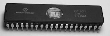
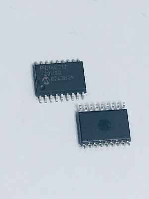
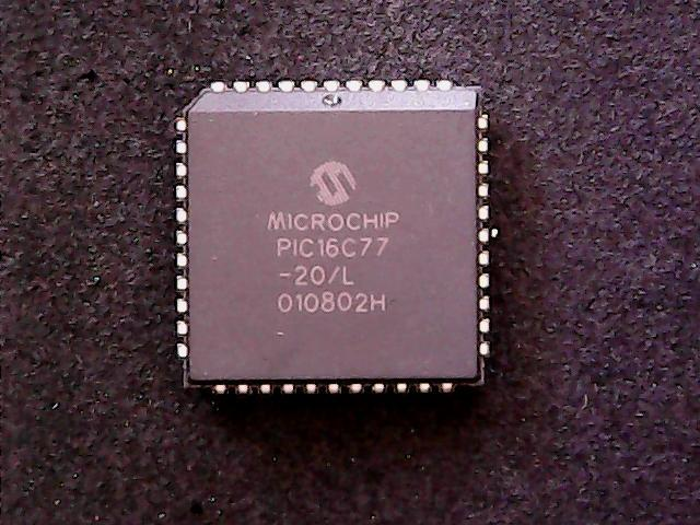
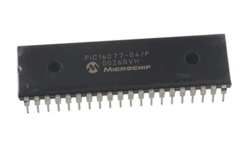
Recover Chip PIC16C77 Code
The PIC16C77 stands as a robust pillar in the world of 8-bit embedded control, specifically engineered for high-end applications requiring extensive I/O and sophisticated timing functions. This versatile MCU is a critical component in various high-stakes industries, including aerospace instrumentation, heavy industrial robotics, and advanced telecommunication switching systems. Its unique features—such as a large memory space for its era and high-speed execution—make it indispensable for managing complex data streams and real-time control algorithms. However, because these chips often utilize protective security bits to keep the internal firmware locked, many organizations find themselves in a precarious position when a device fails or the original source code is lost, leaving the secured logic unreachable through conventional means.
Our high-tech laboratory provides a specialized pathway to break through these hardware-level barriers and retrieve the essential binary archive that keeps your systems operational. To successfully attack a secured MCU, our specialists often use advanced physical techniques to decapsulate the silicon die, allowing for a precise micro-analysis of the protected logic gates. This method enables us to decode the heximal data directly from the internal flash or eeprom layers without destroying the underlying intelligence. Whether the goal is to clone a legacy controller to prevent factory downtime or duplicate the program from an encrypted chip for security auditing, our service provides the technical bridge to hack the limitations of embedded silicon. By focusing on the PIC16C77 architecture, we ensure that every locked file or program is recovered with surgical accuracy, transforming a “black box” back into a usable source code asset.
There are actually two 8-bit latches, one for data-out (from the PIC16/17) and one for data input. The user writes 8-bit data to PORTD data latch and reads data, Chip Select from the port pin latch (note that they have the same address). In this mode, the TRISD register is ignored, since the microprocessor is controlling the direction of A write to the PSP occurs when both the CS and WR lines are first detected low. When either the CS or WR lines become high (level triggered), then the Input Buffer Full status flag bit IBF (TRISE<7>) is set on the Q4 clock cycle, following the next Q2 cycle, to signal the write is complete (Figure 5-12). The interrupt flag bit PSPIF (PIR1<7>) is also set on the same Q4 clock cycle. IBF can only be cleared by reading the PORTD input latch. The input Buffer Overflow status flag bit IBOV (TRISE<5>) is set if a second write to the Parallel Slave Port is attempted when the previous byte has not been read out of the buffer.
A read from the PSP occurs when both the CS and RD lines are first detected low. The Output Buffer Full status flag bit OBF (TRISE<6>) is cleared immediately (Figure 5-13) indicating that the PORTD latch is waiting to be read by the external bus before Recover Chip PIC16C77 Code.
When either the CS or RD pin becomes high (level triggered), the interrupt flag bit PSPIF is set on the Q4 clock cycle, following the next Q2 cycle, indicating that the read is complete. OBF remains low until data is written to PORTD by the user firmware.
When not in Parallel Slave Port mode, the IBF and OBF bits are held clear. However, if flag bit IBOV was previously set, it must be cleared in firmware. An interrupt is generated and latched into flag bit PSPIF when a read or write operation is completed. PSPIF must be cleared by the user in firmware and the interrupt can be disabled by clearing the interrupt enable bit PSPIE (PIE1<7>).
The Timer0 module is a simple 8-bit overflow counter.
The clock source can be either the internal system clock (Fosc/4) or an external clock. When the clock CCP Overview source is an external clock, the Timer0 module can be selected to increment on either the rising or falling edge.
The Timer0 module also has a programmable prescaler option. This prescaler can be assigned to either the Timer0 module or the Watchdog Timer. Bit PSA (OPTION<3>) assigns the prescaler, and bits PS2:PS0 (OPTION<2:0>) determine the prescaler value. Timer0 can increment at the following rates: 1:1 (when pres-caler assigned to Watchdog timer), 1:2, 1:4, 1:8, 1:16, 1:32, 1:64, 1:128, and 1:256 (Timer0 only) if Recover Chip PIC16C77 Code.
Synchronization of the external clock occurs after the prescaler. When the prescaler is used, the external clock frequency may be higher then the device’s frequency. The maximum frequency is 50 MHz, given the high and low time requirements of the clock Timer1 is a 16-bit timer/counter.
The clock source can be either the internal system clock (Fosc/4), an external clock, or an external crystal. Timer1 can operate as either a timer or a counter. When operating as a counter (external clock source) when Recover Chip, the counter can either operate synchronized to the device or asynchronously to the device. Asynchronous operation allows Timer1 to operate during sleep, which is useful for applications that require a real-time clock as well as the power savings of SLEEP mode.
Timer1 also has a prescaler option which allows Timer1 to increment at the following rates: 1:1, 1:2, 1:4, and 1:8. Timer1 can be used in conjunction with the Capture/Compare/PWM module. When used with a CCP module, Timer1 is the time-base for 16-bit Capture or the 16-bit Compare and must be synchronized to the device after Recover Chip PIC16C77 Code.
The CCP module(s) can operate in one of these three modes: 16-bit capture, 16-bit compare, or up to 10-bit Pulse Width Modulation (PWM). Capture mode captures the 16-bit value of TMR1 into the CCPRxH:CCPRxL register pair. The capture event can be programmed for either the falling edge, rising edge, fourth rising edge, or the sixteenth rising edge of the CCPx pin.
The fundamental purpose of performing a targeted attack to break the security of a protected PIC16C77 is to ensure the continuity of critical infrastructure that would otherwise face forced obsolescence. For many end users, the ability to retrieve a heximal archive from a locked MCU is a strategic necessity that avoids the massive costs associated with a total system redesign. By choosing to decode or hack the secured internal memory, our clients can successfully clone or duplicate their vital firmware onto fresh hardware. This ensures that the binary data remains a functional asset even when the original manufacturer no longer supports the part. Our expertise allows you to duplicate the flash and eeprom contents of any embedded controller, ensuring that your protected logic is preserved for the long term.
Ultimately, our recovery service grants the end user total control over their proprietary technology and hardware lifecycle. Instead of struggling with the impossible task of rewriting ancient source code, you can simply retrieve the heximal file and clone the locked program directly onto a replacement MCU. We specialize in the precision required to decapsulate and attack these high-security chips, ensuring that the binary data is handled with the highest level of integrity. By providing a reliable way to decode and duplicate the firmware of a secured PIC16C77, we turn a protected archive into a living part of your current operations. Our commitment is to ensure that your data, memory, and program files remain accessible, regardless of the protective measures originally placed upon the silicon, giving you the freedom to maintain your equipment on your own terms.
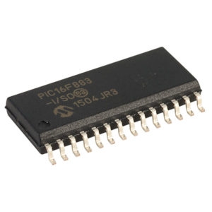
Recover Chip PIC16F883 Eeprom
Recover Chip PIC16F883 Eeprom
Recover Chip PIC16F883 Eeprom and flash memory, it is useful to recover the content from the memory and then make PIC16F883 cloned unit which can replace these broken units:
Low-Power Features:
· Standby Current:
– 50 nA @ 2.0V, typical
· Operating Current:
– 11 ìA @ 32 kHz, 2.0V, typical
– 220 ìA @ 4 MHz, 2.0V, typical
· Watchdog Timer Current:
– 1 ìA @ 2.0V, typical
Peripheral Features:
· 24/35 I/O Pins with Individual Direction Control:
– High current source/sink for direct LED drive
– Interrupt-on-Change pin
– Individually programmable weak pull-ups
– Ultra Low-Power Wake-up (ULPWU)
· Analog Comparator Module
– Two analog comparators
– Programmable on-chip voltage reference (CVREF) module (% of VDD)
– Fixed voltage reference (0.6V)
– Comparator inputs and outputs externally accessible
Recover Chip PIC16F883 Eeprom
– SR Latch mode
– External Timer1 Gate (count enable)
· A/D Converter:
– 10-bit resolution and 11/14 channels
· Timer0: 8-bit Timer/Counter with 8-bit Programmable Prescaler
· Enhanced Timer1:
– 16-bit timer/counter with prescaler
– External Gate Input mode
– Dedicated low-power 32 kHz oscillator
· Timer2: 8-bit Timer/Counter with 8-bit Period Register, Prescaler and Postscaler
· Enhanced Capture, Compare, PWM+ Module:
– 16-bit Capture, max. resolution 12.5 ns
– Compare, max. resolution 200 ns
– 10-bit PWM with 1, 2 or 4 output channels, programmable “dead time”, max. frequency 20 kHz
– PWM output steering control
· Capture, Compare, PWM Module:
– 16-bit Capture, max. resolution 12.5 ns
– 16-bit Compare, max. resolution 200 ns
– 10-bit PWM, max. frequency 20 kHz
· Enhanced USART Module:
– Supports RS-485, RS-232, and LIN 2.0
– Auto-Baud Detect
– Auto-Wake-Up on Start bit
· In-Circuit Serial ProgrammingTM (ICSPTM) via Two Pins
· Master Synchronous Serial Port (MSSP) Module supporting 3-wire SPI (all 4 modes) and I2C™
Master and Slave Modes with I2C Address Mask
Recover Microcontroller PIC16F71 Binary
Recover Microcontroller PIC16F71 Binary
Recover Microcontroller PIC16F71 Binary from its memory which include flash and eeprom, then transfer it to other blank Microcontroller PIC16F71 which will provide the same functions:
GENERAL INSTRUCTION
All PIC16/17 microcontrollers employ an advanced RISC architecture. The PIC16CXX microcontroller family has enhanced core features, eight-level deep stack, and multiple internal and external interrupt sources.
The separate instruction and data buses of the Harvard architecture allow a 14-bit wide instruction word with the separate 8-bit wide data. The two stage instruction pipeline allows all instructions to execute in a single cycle, except for program branches which require two cycles.
Recover Microcontroller PIC16F71 Binary
A total of 35 instructions (reduced instruction set) are available. Additionally, a large register set gives some of the architectural innovations used to achieve a very high performance.
The PIC16C710/71 devices have 36 bytes of RAM, the PIC16C711 has 68 bytes of RAM and the PIC16C715 has 128 bytes of RAM. Each device has 13 I/O pins. In addition a timer/counter is available. Also a 4-channel high-speed 8-bit A/D is provided if recover microcontroller. The 8-bit resolution is ideally suited for applications requiring low-cost analog interface, e.g. thermostat control, pressure sensing.
Recover Microcontroller PIC16F506 Binary
The PIC12F510/16F506 devices from Microchip Technology are low-cost, high-performance, 8-bit, fully-static, Flash-based CMOS microcontrollers. They employ a RISC architecture with only 33 single-word/single-cycle instructions which can faciliate the process of Recover Microcontroller PIC16F506 Binary. All instructions are single-cycle except for program branches, which take two cycles.
The PIC12F510/16F506 devices deliver performance in an order of magnitude higher than their competitors in the same price category. The 12-bit wide instructions are highly symmetrical, resulting in a typical 2:1 code compression over other 8-bit microcontrollers in its class. The easy-to-use and easy-to-remember instruction set reduces development time significantly.
The PIC12F510/16F506 products are equipped with special features that reduce system cost and power requirements. The Power-on Reset (POR) and Device Reset Timer (DRT) eliminate the need for external Reset circuitry.
There are four oscillator configurations to choose from (six on the PIC16F506) when Recover Microcontroller, including INTOSC Internal Oscillator mode and the power-saving LP (Low-power) Oscillator mode. Power-saving Sleep mode, Watchdog Timer and code protection features improve system cost, power and reliability.
The PIC12F510/16F506 devices allow the customer to take full advantage of Microchip’s price leadership in Flash programmable microcontrollers, while benefiting from the Flash programmable flexibility.
The PIC12F510/16F506 products are supported by a full-featured macro assembler, a software simulator, an in-circuit emulator, a ‘C’ compiler, a low-cost development programmer and a full featured programmer. All the tools are supported on IBM® PC and compatible machines.
The PIC12F510/16F506 devices fit in applications ranging from personal care appliances and security systems to low-power remote transmitters/receivers.
The Flash technology makes customizing application programs (transmitter codes, appliance settings, receiver frequencies, etc.) extremely fast and convenient for Recover Microcontroller PIC16F506 Binary. The small footprint packages, for through hole or surface mounting, make these microcontrollers perfect for applications with space limitations.
Low-cost, low power, high-performance when Recover Microcontroller, ease-of-use and I/O flexibility make the PIC12F510/16F506 devices very versatile, even in areas where no microcontroller use has been considered before (e.g., timer functions, logic and PLDs in larger systems and coprocessor applications). significantly.
The PIC12F510/16F506 products are equipped with special features that reduce system cost and power requirements. The Power-on Reset (POR) and Device Reset Timer (DRT) eliminate the need for external Reset circuitry.
There are four oscillator configurations to choose from (six on the PIC16F506), including INTOSC Internal Oscillator mode and the power-saving LP (Low-power) Oscillator mode. Power-saving Sleep mode, Watchdog Timer and code protection features improve system cost, power and reliability.
The PIC12F510/16F506 devices allow the customer to take full advantage of Microchip’s price leadership in Flash programmable microcontrollers, while benefiting from the Flash programmable flexibility.
The PIC12F510/16F506 products are supported by a full-featured macro assembler, a software simulator, an in-circuit emulator, a ‘C’ compiler, a low-cost development programmer and a full featured programmer. All the tools are supported on IBM® PC and compatible machines.
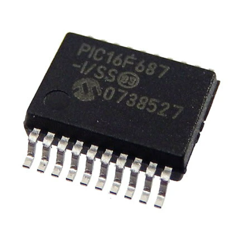
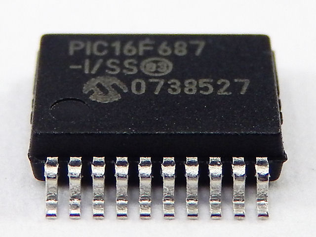
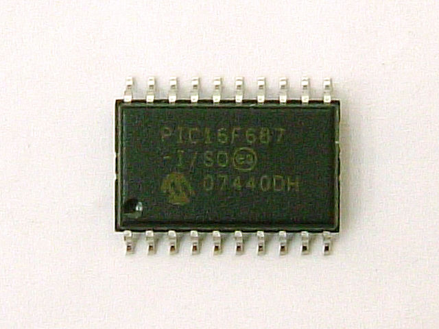
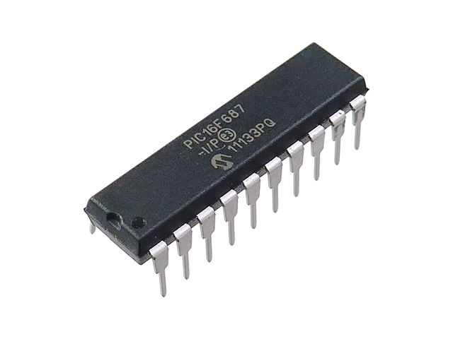
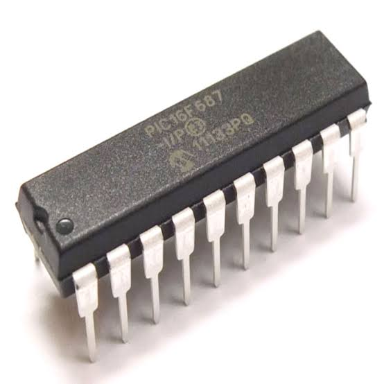
Recover IC PIC16F687 Software
The PIC16F687 is a versatile powerhouse within the mid-range 8-bit microcontroller family, celebrated for its high density of analog peripherals and flexible digital communication interfaces. This specific integrated circuit is frequently deployed in demanding environments such as industrial motor control, environmental monitoring stations, and sophisticated handheld instrumentation. Its distinct advantage lies in its balance of power efficiency and a robust embedded architecture, featuring a sizable flash memory and a dedicated eeprom for critical data retention. Despite its utility, many of these units are deployed with locked security bits to safeguard proprietary logic. When a controller fails or the original development team is no longer available, the secured nature of the chip can prevent standard diagnostics, leaving the protected binary archive unreachable through traditional debugging ports.
Our premier technical laboratory provides a specialized solution to break through these silicon-level restrictions and retrieve the vital software that drives your hardware. By employing a high-precision process to decapsulate the ceramic or plastic housing, our experts gain physical access to the internal logic gates and memory arrays. This allows us to surgically attack the protective fuses and decode the heximal data directly from the protected flash segments. Whether you need to clone an obsolete PLD or duplicate the firmware of a secured controller to ensure production continuity, our non-destructive extraction methods guarantee the integrity of the binary file. This professional capability allows users to hack past the physical and logical barriers of the embedded chip, transforming a locked program back into a functional source code resource.

The Program Counter (PC) is 13 bits wide. The low byte comes from the PCL register, which is a recoverable and writable register which can be used for Recover IC PIC16F687 Software. The high byte (PC<12:8>) is not directly recoverable or writable and comes from PCLATH. On any Reset, the PC is cleared. Figure 2-9 shows the two situations for the loading of the PC. The upper example in Figure 2-9 shows how the PC is loaded on a write to PCL (PCLATH<4:0> → PCH). The lower example in Figure 2-9 shows how the PC is loaded during aCALL or GOTO instruction (PCLATH<4:3> → PCH).
The PIC16F687 devices have an 8-level x 13-bit wide hardware stack. The stack space is not part of either program or data space and the Stack Pointer is not recoverable or writable. The PC is PUSHed onto the stack when a CALL instruction is executed or an interrupt causes a branch. The stack is POPed in the event of a RETURN, RETLW or a RETFIE instruction execution. PCLATH is not affected by a PUSH or POP operation.
The stack operates as a circular buffer. This means that after the stack has been PUSHed eight times, the ninth push overwrites the value that was stored from the first push. The tenth push overwrites the second push (and so on).
Executing any instruction with the PCL register as the destination simultaneously causes the Program Counter PC<12:8> bits (PCH) to be replaced by the contents of the PCLATH register. This allows the entire contents of the program counter to be changed by writing the desired upper 5 bits to the PCLATH register.
When the lower 8 bits are written to the PCL register, all 13 bits of the program counter will change to the values contained in the PCLATH register and those being written to the PCL register after Recover IC PIC16F687 Software.
Circuit Engineering Company Limited continues to be recognized as the Southern China Leader in Services for IC recovering. With the advancement of today’s modern circuit board technology, it is more important than ever to have specialists available to help you at a moment’s notice. Our engineering and commercial teams collectively have a vast amount of electronic experience covering field include Consumer Electronics, Industrial Automation Electronics, Wireless Communication Electronics., etc. For more information please contact us through email.
The fundamental objective of choosing to attack or break the security of a PIC16F687 is to protect long-term investments in specialized equipment. In industries where hardware longevity is measured in decades, the ability to retrieve a heximal archive from a protected device is the only way to clone or duplicate essential components when the supply chain falters. By choosing to decode or hack the secured internal memory, our clients can successfully migrate their program data to new hardware without the astronomical costs of redesigning the entire system. Our service ensures that the encrypted or locked source code remains an accessible asset, providing a reliable path to duplicate the flash and eeprom contents of any embedded controller, regardless of its original security status.
For the end user, our recovery service offers a significant competitive edge by drastically shortening repair timelines and preserving intellectual property. Instead of struggling with lost documentation, you can simply retrieve the heximal file and clone the locked program directly onto a replacement unit. We bridge the gap between a protected binary program and a restored, operational machine, ensuring that your secured data and firmware are never permanently out of reach. By utilizing our expertise to decapsulate and attack the hardware locks of the PIC16F687, you ensure that every file and archive is preserved with total accuracy. This comprehensive approach to embedded recovery provides the ultimate peace of mind for organizations relying on protected silicon to maintain their critical infrastructure.
Recover IC PIC16F72A Binary
Recover IC PIC16F72A Binary
This document contains device-specific information for Recover IC PIC16F72A Binary. Additional information may be found in the PICmicro™ Mid-Range Reference Manual, (DS33023), which may be obtained from your local Microchip Sales Representative or downloaded from the Microchip website.
The Reference Manual should be considered a complementary document to this data sheet, and is highly recommended reading for a better understanding of the device architecture and operation of the peripheral modules. There are two devices (PIC16C72A) covered by this datasheet. The PIC16C72A does not have the A/D module implemented.
The Special Function Registers are registers used by the CPU and Peripheral Modules for controlling the desired operation of the device. These registers are implemented as static RAM.
The STATUS register, shown in Register 2-1, contains the arithmetic status of the ALU, the RESET status and the bank select bits for data memory.
The STATUS register can be the destination for any instruction, as with any other register. If the STATUS register is the destination for an instruction that affects the Z, DC or C bits, the write to these three bits is disabled after Recover IC PIC16F72A Binary.
These bits are set or cleared according to the device logic. The TO and PD bits are not writable. The result of an instruction with the STATUS register as destination may be different than intended.
For example, CLRF STATUS will clear the upper-three bits and set the Z bit. This leaves the STATUS register as 000u u1uu (where u = unchanged).
Circuit Engineering Company Limited continues to be recognized as the Southern China Leader in Services for IC Read, MCU Recover, Chip Extract, Microcontroller Unlock service. With the advancement of today’s modern circuit board technology, it is more important than ever to have specialists available to help you at a moment’s notice.
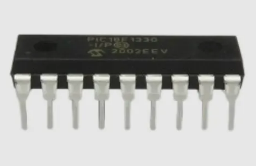
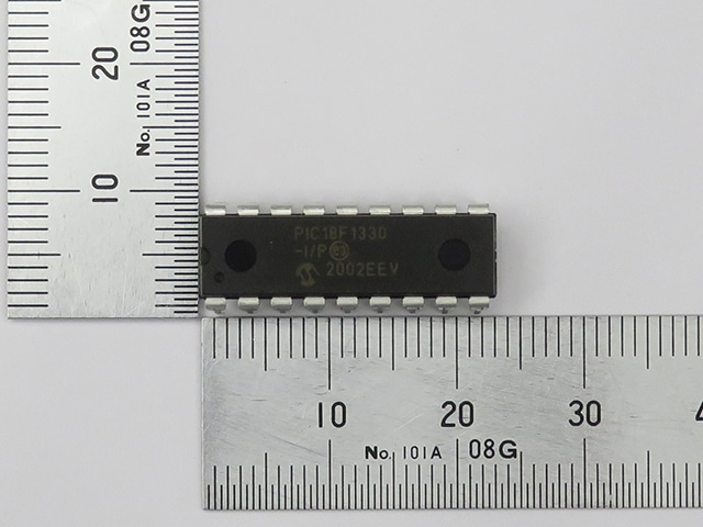
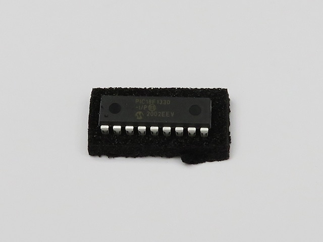
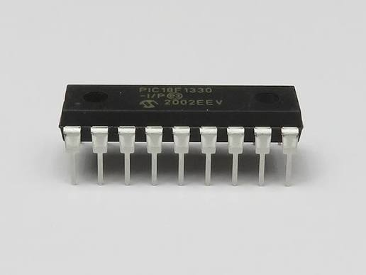
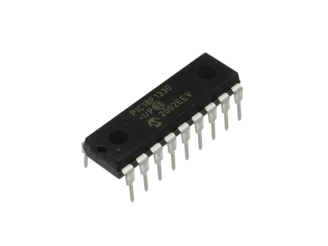
Recover Chip PIC18F1330 Code
The PIC18F1330 is a high‑performance 8‑bit microcontroller from Microchip, featuring 8KB of flash program memory, 256 bytes of EEPROM data storage, and 256 bytes of SRAM. It also includes a unique high‑voltage program interface and a built‑in motor control PWM module, making it ideal for automotive power windows, industrial servo drives, robotic actuators, and medical pump controllers. Unlike standard chips, the PIC18F1330 integrates embedded peripherals that require precisely tuned firmware to operate safely. Manufacturers often set protective lock bits to prevent unauthorised readout, turning the microcontroller into a secured black box. When the original source code is lost or the vendor discontinues support, the only archive of the binary file remains trapped inside the locked memory. Recovering that data becomes essential to avoid scrapping expensive equipment.
Memory Endurance: The Enhanced Flash cells for both program memory and data EEPROM are rated to last for many thousands of erase/write cycles – up to 100,000 for program memory and 1,000,000 for EEPROM. Data retention without refresh is conservatively estimated to be greater than 40 years.
Self-Programmability: These devices can write to their own program memory spaces under internal software control. By using a boot loader routine located in the protected Boot Block at the top of program memory, it becomes possible to create an application that can update itself in the field.
To recover the firmware from a locked PIC18F1330, one cannot simply use a standard programmer because the protective encrypted lock bits block any readout of the flash or EEPROM. Our service employs advanced techniques to break this protection. First, we may decapsulate the chip using precision etching to expose the silicon die, then hack into the memory array via micro‑probing. Alternatively, we utilise fault injection or side‑channel analysis to decode the secured program without destroying the microcontroller. The goal is to retrieve the complete binary or heximal file that contains the original source code logic. Once extracted, we can clone or duplicate this firmware into a fresh PIC18F1330 chip, effectively restoring the embedded software. This attack on the protected memory does not alter the original data; it simply makes the archive accessible for legitimate maintenance and reverse engineering.
· Extended Instruction Set: The PIC18F1230/1330 family introduces an optional extension to the PIC18 instruction set, which adds eight new instructions and an Indexed Addressing mode. This extension, enabled as a device configuration option, has been specifically designed to optimize re-entrant application code originally developed in high-level languages, such as C.
· Power Control PWM Module: This module provides up to six modulated outputs for controlling half-bridge and full-bridge drivers. Other features include auto-shutdown on Fault detection and auto-restart to reactivate outputs once the condition has cleared.
· Enhanced Addressable USART: This serial communication module is capable of standard RS-232 operation and provides support for the LIN bus protocol. Other enhancements include automatic baud rate detection and a 16-bit Baud Rate Generator for improved resolution from Recover Chip PIC18F1330 Code.
The market demand for recover services comes from three real‑world situations. First, obsolete equipment: many industrial motor drives and automotive modules still rely on the PIC18F1330, but the original source code file was lost when a supplier went bankrupt. Second, embedded firmware corruption: a flash memory bit‑flip can render the program non‑functional, and without a backup binary, the entire system stops. Third, reverse engineering for compatibility: companies need to clone a secured microcontroller to produce drop‑in replacements. By performing a clean decode and retrieve of the heximal archive, we enable clients to duplicate the program into new chips, avoiding costly redesigns. The benefit is tangible: extended product lifecycle, reduced e‑waste, and preserved intellectual property.
When the microcontroller is using the internal oscillator block, the EUSART provides stable operation for applications that talk to the outside world without using an external crystal (or its accompanying power requirement).
· 10-Bit A/D Converter: This module incorporates programmable acquisition time, allowing for a channel to be selected and a conversion to be initiated without waiting for a sampling period and thus, reducing code overhead.
· Extended Watchdog Timer (WDT): This enhanced version incorporates a 16-bit prescaler, allowing an extended time-out range that is stable across operating voltage and temperature.
See Section 22.0 “Electrical Characteristics” for time-out periods. Devices in the PIC18F1230/1330 family are available in 18-pin, 20-pin and 28-pin packages. The devices are differentiated from each other in one way:
1. Flash program memory (4 Kbytes for PIC18F1230, 8 Kbytes for PIC18F1330). All other features for devices in this family are identical. Like all Microchip PIC18 devices, members of the PIC18F1230/1330 family are available as both standard and low-voltage devices.
Standard devices with Enhanced Flash memory, designated with an “F” in the part number (such as PIC18F1330), accommodate an operating VDD range of 4.2V to 5.5V. Low-voltage parts, designated by “LF” (such as PIC18LF1330), function over an extended VDD range of 2.0V to 5.5V.
We offer confidential, fast, and professional recover services for the PIC18F1330 and many other microcontrollers. Every break procedure is performed with care to preserve the data integrity. Contact us with your locked chip, and we will decapsulate, decode, and retrieve the complete binary or heximal file – turning a protective memory into a usable archive for production, maintenance, or cloning.