 Extract DSP CPLD Encrypted Software
 June 21st, 2013 |
  Author:
 Extract DSP CPLD Encrypted Software from memory start from disable the tamper resistance, by using MCU invasive cracking will help to disclose the internal structure of CPLD chip;
Extract DSP CPLD Encrypted Software from memory start from disable the tamper resistance, by using MCU invasive cracking will help to disclose the internal structure of CPLD chip
When it comes to reverse engineering smartcards and microcontrollers, both structural and program-code reverse engineering are required to understand how the device works. First, the security protection needs to be understood by partial reverse engineering of the chip area associated with it. Thus if memory bus encryption was used, the hardware responsible for this should be reverse engineered. Then, finally, the internal memory contents have to be extracted and disassembled to understand device functions.
 Posted in
  Tags:
Tags: 
Crack Lattice CPLD Embeded Firmware
Crack Lattice CPLD Embeded Firmware from its memory, copy jed content to blank Lattice CPLD which will provide the same functions as original master CPLD, this microcontroller security unlocking technique can help engineer to extract jed file from master CPLD.
Crack Lattice CPLD Embeded Firmware from its memory, copy jed content to blank Lattice CPLD which will provide the same functions as original master CPLD.
Reverse engineering is a technique aimed at understanding the structure of a semiconductor device and its functions. In case of an ASIC or a custom IC, that means extracting information about the location of all the transistors and interconnections. In order to succeed, a general knowledge of IC and VLSI design is required.
All the layers formed during chip fabrication are removed one-by-one in reverse order and photographed to determine the internal structure of the chip. In the end, by processing all the acquired information, a standard netlist file can be created and used to simulate the device. This is a tedious and time-consuming process, but there are some companies, for example Chipworks [110], which do such work as a standard service.
Crack DSP CPLD IC Chip File
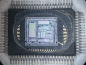
Crack DSP CPLD IC Chip Memory and extract file from DSP Chip flash memory, DSP IC cracking process normally start from decapsulate the silicon package of CPLD chip;
Crack DSP CPLD IC Chip Memory and extract file from DSP Chip flash memory, DSP IC cracking process normally start from decapsulate the silicon package of CPLD chip
For wet chemical etching we used the Nitrox wet etchant – one of the most effective etching agents for silicon nitride and silicon dioxide passivation layers which selectively removes the passivation layers of integrated circuits while preserving full device functionality.
To observe deeper layers, top aluminium layers were etched away with a 20% water solution of hydrochloric acid HCl or 33% water solution of potassium hydroxide KOH. Although wet etching does not provide good uniformity across the die surface, a lot of information about the internal chip structure can be obtained. Examples of such operations are presented
As can be seen, wet chemical etching does not provide very good uniformity over the surface resulting in some areas where the top metal is not entirely removed and other areas where the underneath layer is starting to be etched. Also, as can be seen in Figure 57, some long metal wires lifted off the surface obstructing the view.
Deprocessing using wet chemical etching does not require much more experience than decapsulation and all the necessary chemicals can be bought for about £100. Care must be taken during the work, as these chemicals are very aggressive and dangerous, especially the ones containing fluorine.
Crack Microcontroller IC Source Code
A microcontroller is often the central control element of an electronic product, combining processing capability, peripheral interfaces, and non-volatile storage in a compact device. Across industrial automation, automotive electronics, medical equipment, telecommunications, consumer appliances, security systems, instrumentation, and specialized control equipment, an embedded microcontroller or MCU may contain years of valuable engineering development. Depending on the architecture, application firmware, configuration data, and executable program information can reside in internal flash, eeprom, or other memory resources.
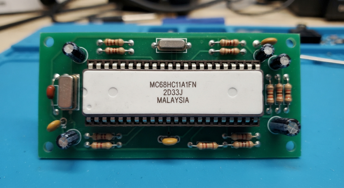
When the original development environment is lost, recovering information from an existing IC can become important for maintenance and product continuity. Our “crack microcontroller ic source code” service is designed for authorized customers who need to investigate existing hardware, preserve embedded software assets, and reconstruct engineering information from legacy products. Because the original source code is not normally stored literally inside every microcontroller, professional recovery may involve analysis of available binary, heximal, firmware, configuration data, and surrounding hardware behavior rather than simply copying a source-code file.
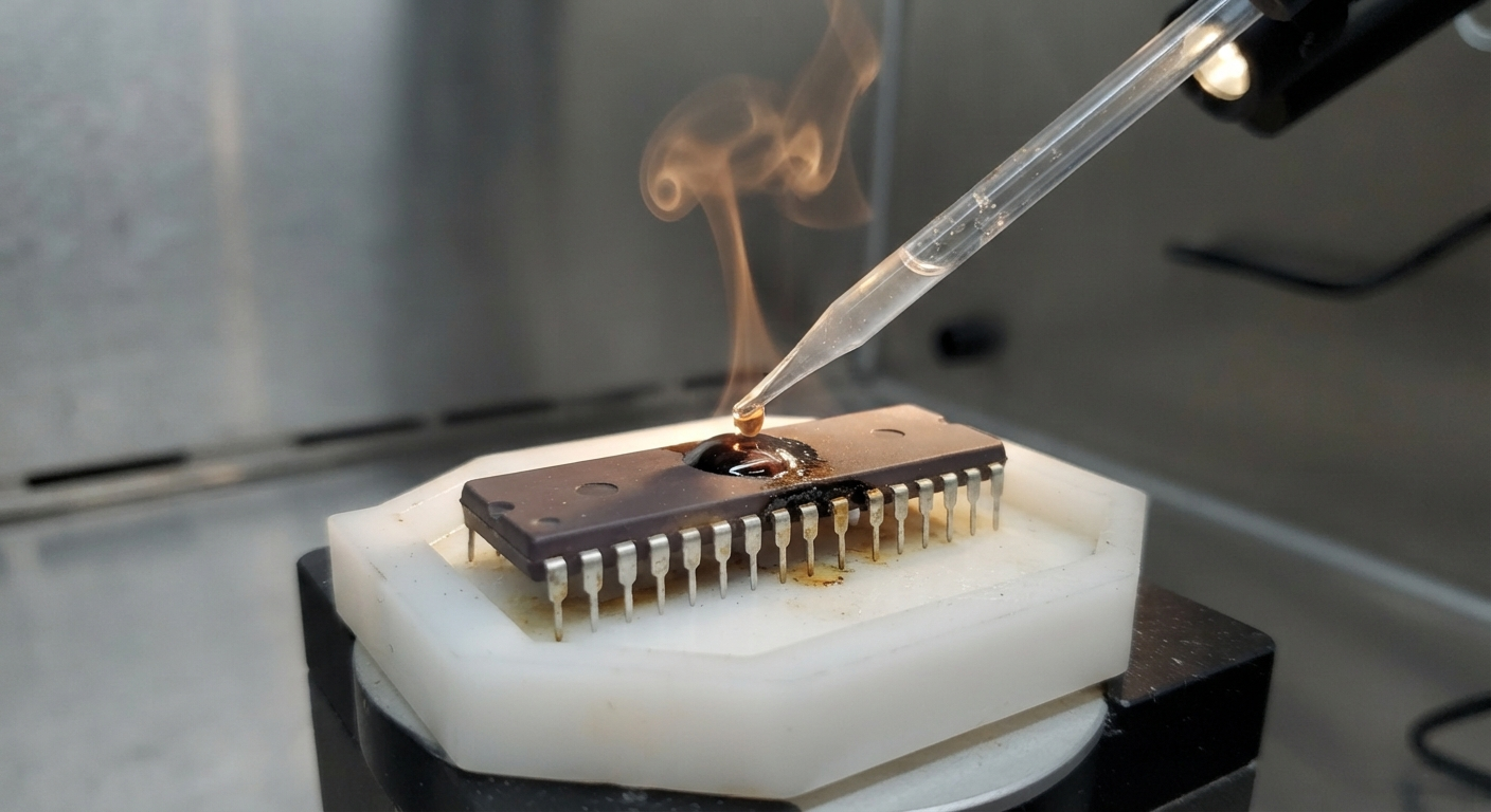
For wet and dry etching, each type of material requires certain etchants to be used. Some of them have very high selectivity and remove only the desired layer; others affect many layers at a time. For example, silicon and polysilicon can be etched with a mixture of hydrofluoric acid HF and nitric acid HNO3, but HF etches silicon oxide as well.
Our engineering team approaches each project according to the architecture and condition of the target microprocessor, MCU, or IC. The first stage is a technical assessment of the device, PCB, available documentation, and storage configuration. Engineers then determine whether useful firmware, binary, heximal, program, or configuration data can be retrieved from the available memory. Depending on the semiconductor technology, advanced laboratory analysis may include carefully controlled decapsulate examination to investigate internal structures when conventional access is insufficient.
Recovered information can be processed and decoded into organized engineering file and archive resources, while software analysis can help reconstruct program behavior and produce a practical representation of the original design. Customers may refer to this work as attack, break, or hack, particularly when a device has protective, protected, locked, secured, or encrypted storage. In professional engineering work, however, the purpose is authorized recovery and preservation rather than unauthorized intrusion. Where technically feasible, the resulting information may support controlled clone evaluation, duplicate development, troubleshooting, redesign, or migration to a replacement platform.
Other etchants are used for specific purposes, such as doping etchants with a doping-dependent etch rate to make visible doping fronts and p-n junctions. Such etchants are used, for example, to make visible the contents of VTROM in modern smartcards [8]. More information about different etchants and etching technology can be found in the literature on failure analysis techniques.
Recovering embedded software requires more than obtaining a raw memory image. Engineers must establish whether the recovered binary is complete, determine which sections represent executable program information, and distinguish application firmware from configuration parameters or unrelated storage areas. Hardware behavior provides an important reference during this process: signal activity, peripheral functions, communication interfaces, and system responses can help correlate recovered data with the original application.
For a locked or encrypted device, the achievable result depends on the specific architecture and protection mechanism, so no universal recovery method can be assumed. Where appropriate, semiconductor-level analysis can complement conventional firmware investigation and help clarify the relationship between the physical IC and its embedded information. The final engineering package may therefore contain a recovered firmware image, validated binary or heximal files, reconstructed program documentation, memory maps, functional observations, and organized archive records rather than literal original source code.
For manufacturers, repair companies, engineering organizations, and authorized product owners, professional microcontroller source-code recovery can provide substantial lifecycle advantages. Instead of recreating a mature electronic product entirely from the beginning, engineering teams can use recovered firmware, program information, and technical documentation as a foundation for maintenance and modernization.
This can reduce redevelopment effort, support discontinued equipment, facilitate replacement-board production, and preserve valuable embedded intellectual property. It can also help organizations migrate an established design to a newer microcontroller while retaining an understanding of the original system behavior. By combining hardware investigation, firmware analysis, semiconductor examination, and structured documentation, our service provides a practical pathway for recovering valuable embedded resources from existing MCU and IC platforms and turning inaccessible engineering information into reusable technical assets.
Reverse Engineering ATmel Chip Atmega8L-8PU
The atmel atmega8l-8pu is one of the most widely recognized 8-bit microcontroller devices used in embedded electronic products over the past two decades. Its low power consumption, flexible peripheral integration, compact architecture, and dependable performance have made this mcu a preferred chip for industrial automation, home appliances, automotive accessories, security systems, intelligent instruments, consumer electronics, access control equipment, communication interfaces, and educational development platforms.
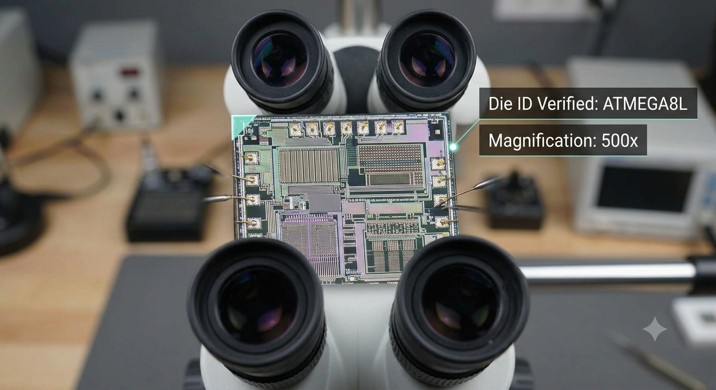
As a highly integrated microprocessor, the device stores operational firmware, application program logic, calibration data, and system configuration inside internal flash, eeprom, and non-volatile memory resources. Many products built around this ic continue to operate reliably long after production has ended, yet manufacturers frequently discover that the original source code, binary, heximal project file, or engineering archive has been lost. Combined with protected, locked, secured, protective, or encrypted memory configurations, maintaining or upgrading these products becomes increasingly difficult without professional reverse engineering support.
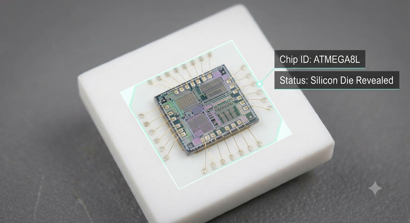
Reverse engineering ATmel Chip Atmega8L-8PU means the content from both its eeprom and flash can be extracted and download it to other blank ATmega8L which will provide the same functions:
High-performance, Low-power AVR 8-bit Microcontroller
· Advanced RISC Architecture
– 130 Powerful Instructions – Most Single-clock Cycle Execution
– 32 x 8 General Purpose Working Registers
– Fully Static Operation
– Up to 16 MIPS Throughput at 16 MHz
– On-chip 2-cycle Multiplier
High Endurance Non-volatile Memory segments
– 8K Bytes of In-System Self-programmable Flash program memory
– 512 Bytes EEPROM
– 1K Byte Internal SRAM
– Write/Erase Cycles: 10,000 Flash/100,000 EEPROM (1)(3)
– Data retention: 20 years at 85°C/100 years at 25°C (2)(3)
– Optional Boot Code Section with Independent Lock Bits
In-System Programming by On-chip Boot Program True Read-While-Write Operation
– Programming Lock for Software Security
Peripheral Features
– Two 8-bit Timer/Counters with Separate Prescaler, one Compare Mode
– One 16-bit Timer/Counter with Separate Prescaler, Compare Mode, and Capture Mode
– Real Time Counter with Separate Oscillator
– Three PWM Channels
– 8-channel ADC in TQFP and QFN/MLF package
Eight Channels 10-bit Accuracy
– 6-channel ADC in PDIP package
Six Channels 10-bit Accuracy
– Byte-oriented Two-wire Serial Interface
– Programmable Serial USART
– Master/Slave SPI Serial Interface
– Programmable Watchdog Timer with Separate On-chip Oscillator
– On-chip Analog Comparator
Special Microcontroller Features
– Power-on Reset and Programmable Brown-out Detection
– Internal Calibrated RC Oscillator
– External and Internal Interrupt Sources
– Five Sleep Modes: Idle, ADC Noise Reduction, Power-save, Power-down, and Standby I/O and Packages
– 23 Programmable I/O Lines from Reverse engineering ATmel Chip Atmega8L-8PU
– 28-lead PDIP, 32-lead TQFP, and 32-pad QFN/MLF Operating Voltages
– 2.7 – 5.5V (ATmega8L)
– 4.5 – 5.5V (ATmega8) Speed Grades
– 0 – 8 MHz (ATmega8L)
– 0 – 16 MHz (ATmega8)
Our “reverse engineering atmel chip atmega8l-8pu” service is specifically developed for authorized recovery and technical analysis of legacy embedded systems. Using advanced laboratory equipment and comprehensive engineering workflows, our specialists evaluate the architecture of the target microcontroller, identify available firmware, and retrieve valuable data from internal flash, eeprom, and other memory resources. Depending on the condition of the chip, carefully controlled decapsulate procedures may be employed to assist semiconductor analysis and improve understanding of the internal storage organization.
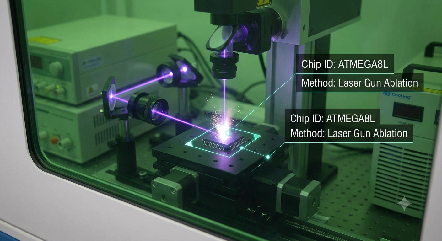
Advanced decode technologies process recovered binary and heximal information, reconstruct fragmented program structures, and organize engineering file collections into structured archive resources. For customer-owned devices that contain protected, locked, or encrypted storage, our engineers conduct systematic analysis to determine the most appropriate recovery strategy. Rather than simply attempting to attack, break, or hack a device, our objective is to preserve valuable engineering assets, rebuild unavailable documentation, and support lawful product maintenance. The resulting engineering information can assist with compatibility studies, controlled clone validation, duplicate production of legacy hardware, software migration, and long-term lifecycle management.
Every reverse engineering project follows a structured methodology that combines hardware investigation with embedded software analysis. Engineers first evaluate the physical condition of the ic, inspect the internal memory organization, and identify relationships between stored firmware, peripheral configuration, and application behavior.
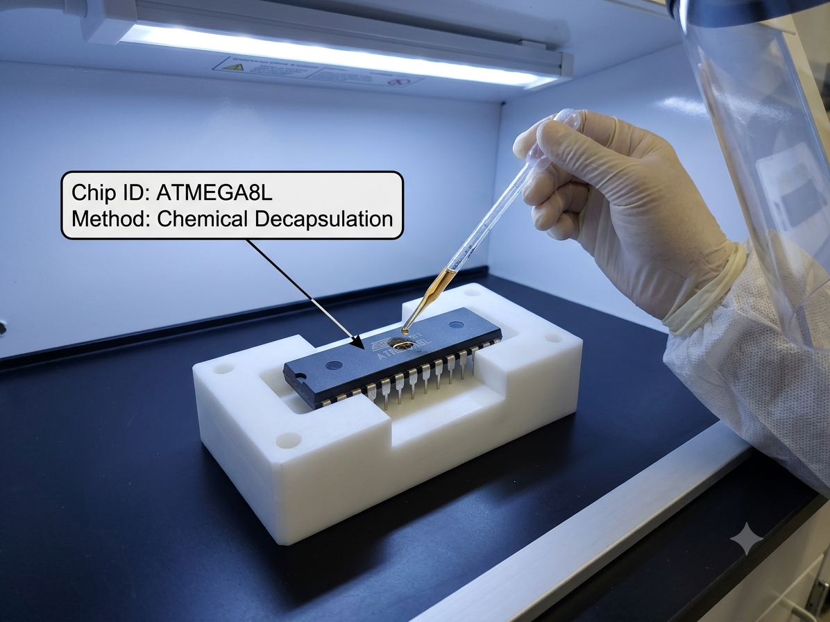
Available binary images and heximal records are validated before specialized software tools decode recovered data into meaningful engineering information. Throughout the reconstruction process, historical program logic, configuration parameters, and available source code references are correlated with observed hardware operation to create reliable technical documentation. When necessary and appropriately authorized, laboratory-level semiconductor analysis, including selective decapsulate procedures, may provide additional insight into difficult-to-access storage structures. This disciplined approach transforms fragmented engineering archive materials into usable resources that support redesign, troubleshooting, product modernization, and documentation of complex embedded systems.
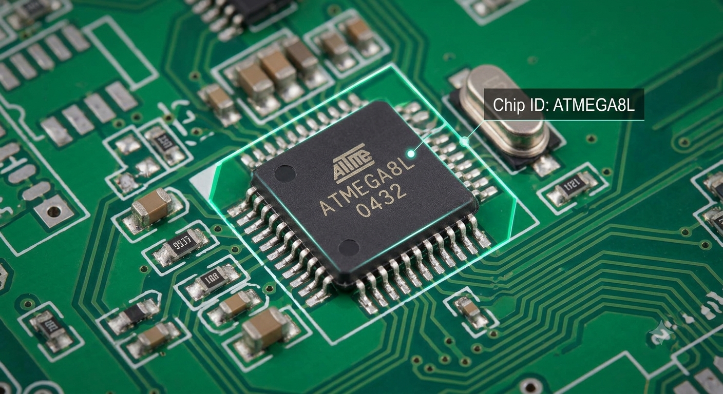
For manufacturers, maintenance providers, and engineering organizations, professional reverse engineering of the atmega8l-8pu offers significant commercial and technical value. Recovering historical firmware, organized binary files, validated data, reconstructed program structures, and archived engineering resources reduces redevelopment costs while extending the service life of proven products.
Companies can preserve valuable intellectual property, support obsolete equipment, improve maintenance efficiency, and migrate existing designs to newer platforms without abandoning years of engineering investment. Backed by extensive experience in atmel microcontroller analysis, embedded firmware recovery, and semiconductor engineering, our service converts inaccessible technical information into practical engineering resources, enabling customers to maintain continuity, improve product reliability, and protect the long-term value of their embedded electronic systems.
Recover TI MSP430G2452 Embedded Memory
Recover TI MSP430G2452 Embedded Memory
Recover TI MSP430G2452 Embedded Memory starts from acquiring its basic structure:
FEATURES
Low Supply Voltage Range: 1.8 V to 3.6 V
Ultra-Low Power Consumption
– Active Mode: 220 µA at 1 MHz, 2.2 V
– Standby Mode: 0.5 µA
– Off Mode (RAM Retention): 0.1 µA
Five Power-Saving Modes
Ultra-Fast Wake-Up From Standby Mode in Less Than 1 µs
16-Bit RISC Architecture, 62.5-ns Instruction Cycle Time
Recover TI MSP430G2452 Embedded Memory
Basic Clock Module Configurations
– Internal Frequencies up to 16 MHz With Four Calibrated Frequencies
– Internal Very-Low-Power Low-Frequency (LF) Oscillator
– 32-kHz Crystal
– External Digital Clock Source One 16-Bit Timer_A With Three Capture/Compare Registers
Up to 16 Touch-Sense Enabled I/O Pins
Universal Serial Interface (USI) Supporting SPI and I2C
recover MCU IC Texas Instruments MSP430G2452IPW14R
recover MCU IC Texas Instruments MSP430G2452IPW14R
10-Bit 200-ksps Analog-to-Digital (A/D)
Converter With Internal Reference, Sample-and-Hold, and Autoscan (MSP430G2x52 Only)
On-Chip Comparator for Analog
Brownout Detector Serial Onboard Programming,
No External Programming Voltage Needed,
Programmable Code Protection by Security Fuse
On-Chip Emulation Logic With Spy-Bi-Wire Interface
Family Members are Summarized in Table 1 Package Options
– TSSOP: 14 Pin, 20 Pin
– PDIP: 20 Pin
– QFN: 16 Pin
For Complete Module Descriptions, See the MSP430x2xx Family User’s Guide (SLAU144)
Break Microcontroller TI TMS320F28232PGFA Protection
The TI TMS320F28232PGFA is a high-performance dsp microcontroller designed for demanding real-time control applications. As a member of the C2000 family, this advanced MCU combines digital signal processing capability with powerful peripheral integration, making it a preferred IC for industrial motor drives, renewable energy inverters, electric vehicle power electronics, robotics, factory automation, digital power supplies, and intelligent instrumentation. Its architecture enables fast mathematical processing while storing critical firmware, application program logic, calibration data, and operating parameters within on-chip flash, memory, and related storage resources.
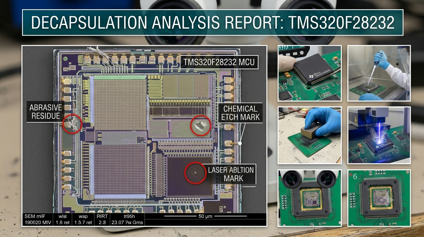
Because these systems often represent years of engineering investment, manufacturers typically configure the device with protective, protected, locked, secured, or encrypted mechanisms to safeguard proprietary software. However, when original engineering records, development file collections, or historical archive resources are no longer available, organizations may require specialized recovery services to preserve valuable embedded technology and maintain long-term product support.
· High-Performance Static CMOS Technology
– Up to 150 MHz (6.67-ns Cycle Time)
– 1.9-V/1.8-V Core, 3.3-V I/O Design
· High-Performance 32-Bit CPU (TMS320C28x)
– IEEE-754 Single-Precision Floating-Point
Unit (FPU) (F2833x only)
– 16 x 16 and 32 x 32 MAC Operations
– 16 x 16 Dual MAC
– Harvard Bus Architecture
– Fast Interrupt Response and Processing
– Unified Memory Programming Model
– Code-Efficient (in C/C++ and Assembly)
· Six-Channel DMA Controller (for ADC, McBSP, ePWM, XINTF, and SARAM)
· 16-Bit or 32-Bit External Interface (XINTF)
– Over 2M x 16 Address Reach
· On-Chip Memory
– F28335, F28235:
256K x 16 Flash, 34K x 16 SARAM
– F28334, F28234:
128K x 16 Flash, 34K x 16 SARAM
– F28332, F28232:
64K x 16 Flash, 26K x 16 SARAM
– 1K x 16 OTP ROM
· Boot ROM (8K x 16)
– With Software Boot Modes (via SCI, SPI, CAN, I2C, McBSP, XINTF, and Parallel I/O)
– Standard Math Tables
· Clock and System Control
– Dynamic PLL Ratio Changes Supported
– On-Chip Oscillator
– Watchdog Timer Module
· GPIO0 to GPIO63 Pins Can Be Connected to One of the Eight External Core Interrupts
· Peripheral Interrupt Expansion (PIE) Block That Supports All 58 Peripheral Interrupts
· 128-Bit Security Key/Lock
– Protects Flash/OTP/RAM Blocks
– Prevents Firmware Reverse Engineering
· Enhanced Control Peripherals
– Up to 18 PWM Outputs
– Up to 6 HRPWM Outputs With 150 ps MEP Resolution
– Up to 6 Event Capture Inputs
– Up to 2 Quadrature Encoder Interfaces
– Up to 8 32-Bit Timers
(6 for eCAPs and 2 for eQEPs)
– Up to 9 16-Bit Timers
(6 for ePWMs and 3 XINTCTRs)
· Three 32-Bit CPU Timers
· Serial Port Peripherals
– Up to 2 CAN Modules
– Up to 3 SCI (UART) Modules
– Up to 2 McBSP Modules (Configurable as SPI)
– One SPI Module
– One Inter-Integrated-Circuit (I2C) Bus
· 12-Bit ADC, 16 Channels
– 80-ns Conversion Rate
– 2 x 8 Channel Input Multiplexer
– Two Sample-and-Hold
– Single/Simultaneous Conversions
– Internal or External Reference
· Up to 88 Individually Programmable, Multiplexed GPIO Pins With Input Filtering
· JTAG Boundary Scan Support (1)
· Advanced Emulation Features
– Analysis and Breakpoint Functions
– Real-Time Debug via Hardware
· Development Support Includes
– ANSI C/C++ Compiler/Assembler/Linker
– Code Composer Studio™ IDE
– DSP/BIOS™
– Digital Motor Control and Digital Power Software Libraries
Low-Power Modes and Power Savings from Break Microcontroller TI TMS320F28232PGFA Protection
– IDLE, STANDBY, HALT Modes Supported
– Disable Individual Peripheral Clocks
· Endianness: Little Endian
· Package Options:
– Lead-free, Green Packaging
– Low-Profile Quad Flatpack (PGF, PTP)
– MicroStar BGA™ (ZHH)
– Plastic BGA (ZJZ)
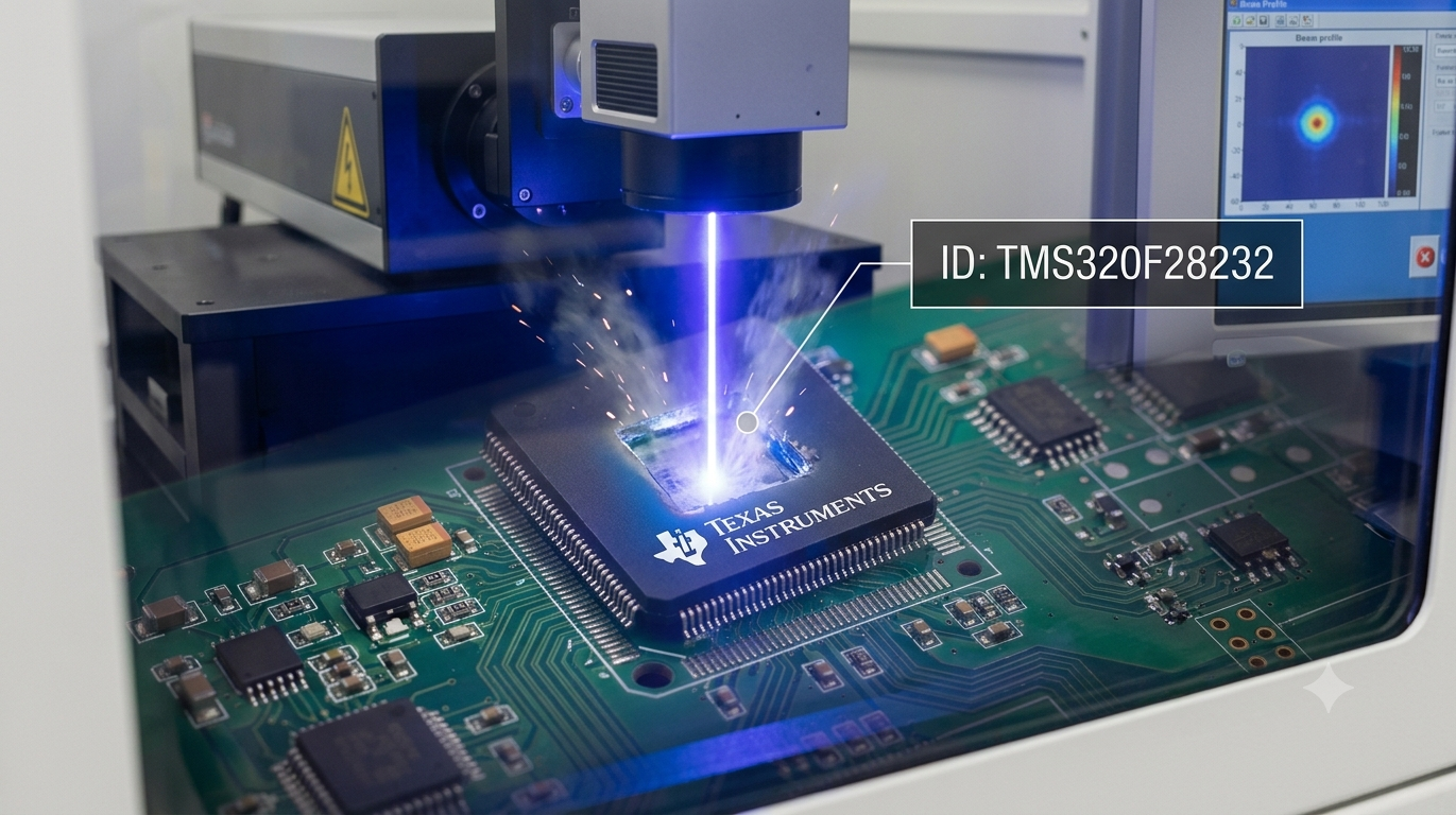
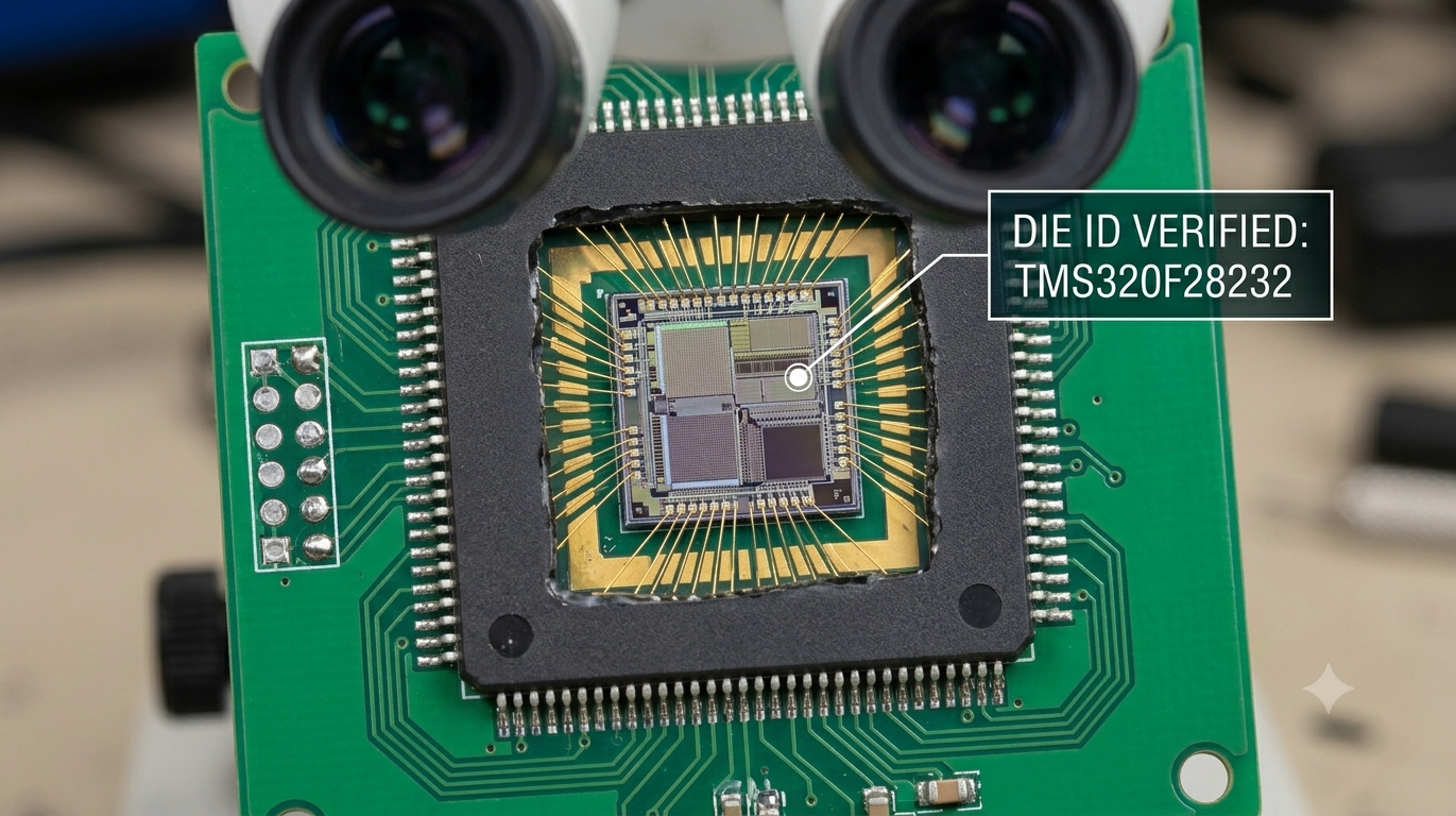
Our “Break Microcontroller TI TMS320F28232PGFA protection” service is intended for authorized engineering projects involving firmware preservation, product lifecycle management, and recovery of customer-owned intellectual property. Our specialists evaluate the internal architecture of the chip, analyze available memory resources, and support the recovery of valuable firmware, configuration data, and engineering documentation. Depending on the device condition and customer authorization, advanced laboratory analysis may include controlled decapsulate procedures and semiconductor inspection to better understand internal storage structures.
Through comprehensive engineering workflows, our team can retrieve available binary and heximal information, organize recovered file structures, and rebuild historical archive resources. Sophisticated decode techniques are applied to interpret recovered program information and reconstruct meaningful source code references where feasible. Projects involving locked, protected, or encrypted devices are assessed individually so that appropriate recovery methodologies can be selected. Rather than simply attempting to attack, break, or hack a security mechanism, our objective is to preserve customer-owned engineering assets, support legacy equipment, and facilitate authorized clone verification or duplicate production for long-term maintenance.
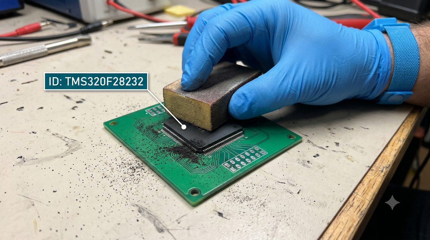
Recovering engineering information from a sophisticated dsp platform requires expertise in both hardware analysis and embedded software architecture. Our workflow begins with a detailed evaluation of the target microprocessor, including its flash, memory, and peripheral organization. Recovered binary images and heximal records are validated before being processed into structured engineering data that accurately reflects the original firmware environment.
Advanced decode procedures help correlate recovered program sections with configuration information, allowing fragmented archive materials to be reconstructed into usable technical resources. Where appropriate, carefully controlled laboratory analysis, including selective decapsulate techniques, can assist engineers in understanding inaccessible storage regions while preserving the integrity of the IC. The resulting firmware, source code references, and engineering files provide valuable insight for hardware migration, documentation rebuilding, compatibility verification, and future product development.

For manufacturers, equipment maintenance providers, and engineering organizations, recovering information from the TMS320F28232PGFA offers substantial practical value. Access to historical firmware, validated binary resources, reconstructed program structures, and organized data archives reduces redevelopment time while extending the service life of proven products.
Organizations can support obsolete equipment, improve technical documentation, migrate designs to newer hardware, and preserve years of engineering investment without redesigning an entire control platform. By combining extensive experience in microcontroller, microprocessor, and dsp analysis with disciplined recovery methodologies, our service transforms inaccessible embedded information into reliable engineering resources that support maintenance, modernization, and long-term continuity for complex electronic systems.
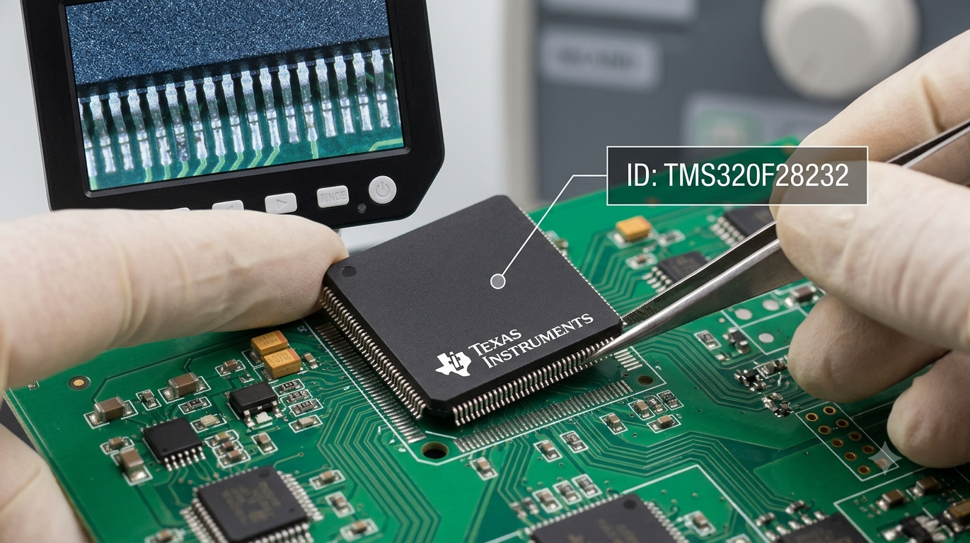
Attack Microchip MCU Embeded Firmware
Attack Microchip MCU protective system and extract Embedded Firmware from microcontroller memory, make Microchip MCU cloning unit by provide the same functions as masters;
Attack Microchip MCU protective system and extract Embedded Firmware from memory, make Microchip MCU cloning unit by provide the same functions as masters;
The removal of material is strongly anisotropic (directional). Only the surfaces hit by the ions are removed, sides perpendicular to their paths are not touched. Mechanical polishing is performed with the use of abrasive materials. The process is time-consuming and requires special machines to maintain the planarity of the surface.
From the inspection perspective, the advantages of using polishing over wet and dry etching techniques is the ability to remove layer by layer and view features in the area of interest within the same plane. It is especially useful on multilayer interconnect processes fabricated with advanced planarisation techniques.
Attack Microchip Microcontroller IC Chip Source Code
Attack Microchip Microcontroller IC Chip starts from deprocessing the external package of MCU, this is a basic technique for MCU crack and Microprocessor Source Code reading;
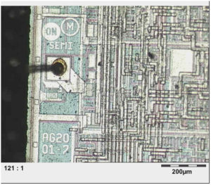
Attack Microchip Microcontroller IC Chip starts from deprocessing the external package of MCU, this is a basic technique for MCU crack and Microprocessor Source Code reading
Three basic deprocessing methods are used: wet chemical etching, plasma etching, also known as dry etching, and mechanical polishing. In chemical etching each layer is removed by specific chemicals. Its downside is its isotropic nature, i.e. uniformity in all directions. That produces unwanted undercutting. As a result, narrow metal lines will have a tendency to lift off the surface.
Isotropic etching also leads to etching through holes such as vias, resulting in unwanted etching of underlaying metallization. Plasma etching uses radicals created from gas inside a special chamber. They react with the material on the sample surface to form volatile products which are pumped out of the chamber. As the ions are accelerated in an electric field they usually hit the surface of the sample perpendicularly.
Microcontroller Cracking Without Part Number
Microcontroller Cracking Without Part Number
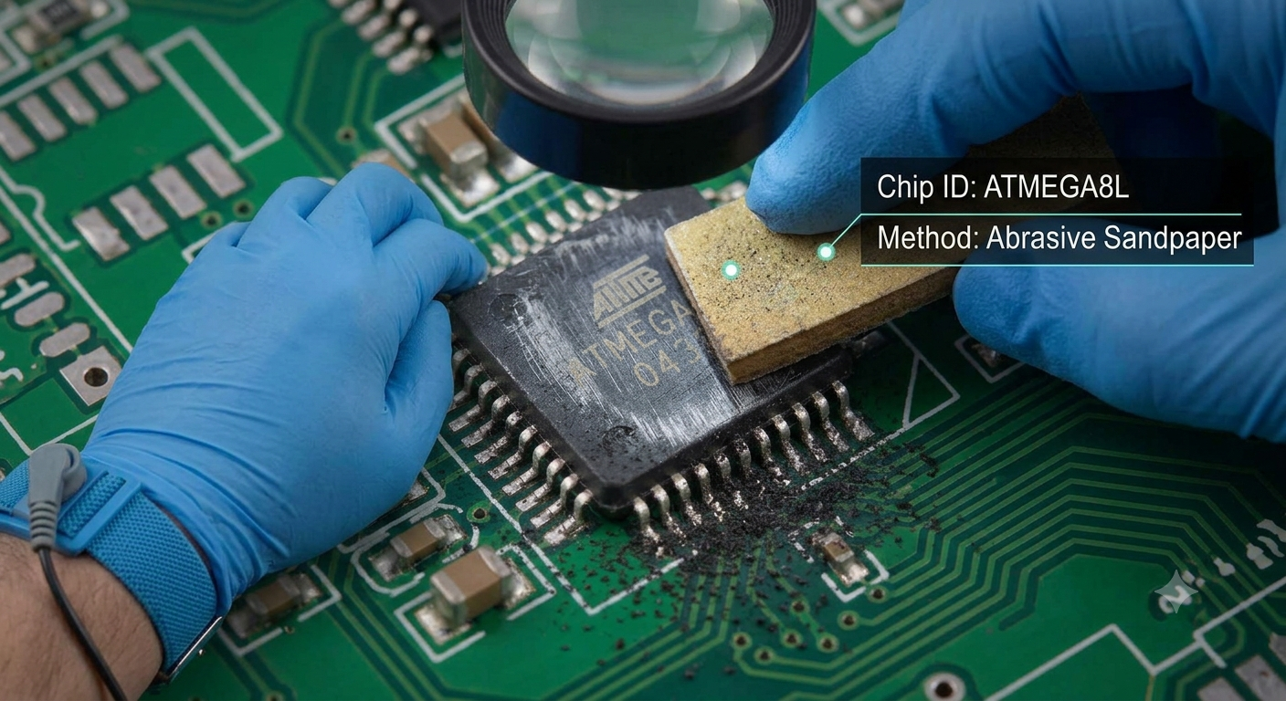
With MCU design and manufacturing technology continues to evolve, Microcontroller cracking method is also emerging, alteration on Microcontroller’s package, erase silkscreen and burn out pins of Microcontroller as well as other methods being applied on electronic devices at home and abroad, erase silkscreen on Microcontroller is the most common method.
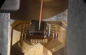
Microcontroller Cracking Without Part Number
For such kind of Microcontroller cracking, must first get to know the exact model number of the Microcontroller, a majority of companies use observation method like assessing the external circuit to estimate the probable models of Microcontroller, due to continuous development of the industry, the limitations of this approach has been growing, mainly in the following several reasons:
1. Because Microcontroller from same company often has compatible pins (for example: MCU from PIC series and MCU of AVR series), so even determine which series of this Microcontroller generously, but still difficult to determine its concrete model;
2. Today, different companies have compatible pins of Microcontroller is also very common (such as EMC78P156 and IC16C54C, etc.), which added more difficult for us to determine the final model number of Microcontroller;
3. Because different companies have different Microcontroller programming port and verified pins distribution, especially the distribution of high-voltage VPP pin is different, so before the Microcontroller model has not been determined, random use of programmer to read the its program (which is currently the most popular approach), it is very likely to cause damage of inside content of flash and eeprom memory.