Break Microcontroller Memory Failure Possibility
 June 8th, 2013 |
  Author:
 Break Microcontroller Memory Failure Possibility
Refers to Break Microcontroller Memory success rate, both our customers and us are all very concerned about this questions, we all want a quick one-time successful microcontroller memory Break, but because crack MCU is not a very simple process, sometimes we may encountered many unforeseen problems, even the same microcontroller memory, designers may use different encryption methods, requires different means to copy the content inside microcontroller memory.
Break Microcontroller Memory Failure Possibility
Here we combine our experience to talk about these possibilities of failure during mcu cracking.
Break Microcontroller Memory do have probability of failure, according to our experience and concerning about the probability, there is about 1% of failure probability when break an microcontroller memory, there is 0.3% probability of damage mother microcontroller memory.
Therefore, we can not either guarantee 100% is successful, or guarantee 100% doesn’t destroy or damage mother microcontroller memory, please carefully take this risk into consideration.
But we conduct a careful summary about the failure of IC clone (those parts involve our core technologies are not listed), and engage in a series of measures to reduce this probability to greatest level, the current probability of failure has become lower and lower, furthermore we promise not charge customers any fees if break microcontroller memory content fail.
 Posted in
Attack Microchip IC MCU Encrypted Code
Attack Microchip IC MCU and extract encrypted code from microcontroller’s memory, program of flash memory and data of eeprom memory will be integrated as a united file called firmware;
Attack Microchip IC MCU and extract encrypted code from microcontroller’s memory, program of flash memory and data of eeprom memory will be integrated as a united file called firmware
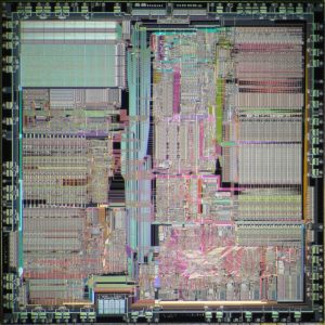
There are two main applications of deprocessing. One is to remove the passivation layer, exposing the top metal layer for microprobing attacks. Another is to gain access to the deep layers and observe the internal structure of the chip.
Recover Microchip PIC18F2423 memory program
Recover Microchip PIC18F2423 Memory Program
Recover Microchip PIC18F2423 memory program includes recover the content from both eeprom and flash, so it is necessary to get a better knowledge of the internal structure:
12-bit,up to 13-channel Analog-to-Digital
Converter module (A/D):
– Auto-acquisition capability
– Conversion available during Sleep
Dualanalog comparators with input multiplexing
High-currentsink/source 25 mA/25 mA
Threeprogrammable external interrupts
Fourinput change interrupts of IC recoverion
Upto 2 Capture/Compare/PWM (CCP) modules, one with Auto-Shutdown (28-pin devices)
EnhancedCapture/Compare/PWM (ECCP) module (40/44-pin devices only):
– One, two or four PWM outputs
– Selectable polarity
– Programmable dead time
– Auto-shutdown and auto-restart
Recover Microchip PIC18F2423 memory program
MasterSynchronous Serial Port (MSSP) module supporting 3-wire SPI (all 4 modes) and I2C™
Master and Slave modes
EnhancedUSART module:
– Supports RS-485, RS-232 and LIN 1.2
– RS-232 operation using internal oscillator block (no external crystal required)
– Auto-wake-up on Start bit
– Auto-Baud Detect
Run:CPU on, peripherals on
Idle:CPU off, peripherals on
Sleep:CPU off, peripherals off
Idlemode currents down to 5.8 ìA, typical
Sleepmode current down to 0.1 ìA, typical
Timer1Oscillator: 1.8 ìA, 32 kHz, 2V
WatchdogTimer: 2.1 ìA
FourCrystal modes, up to 25 MHz
4xPhase Lock Loop (available for crystal and Two-SpeedOscillator Start-up internal oscillators)
TwoExternal RC modes, up to 4 MHz
TwoExternal Clock modes, up to 25 MHz
Internaloscillator block:
– 8 user-selectable frequencies, from 31 kHz to 8 MHz
– Provides a complete range of clock speeds from 31 kHz to 32 MHz when used with PLL
– User-tunable to compensate for frequency drift
Secondaryoscillator using Timer1 @ 32 kHz
Fail-SafeClock Monitor:
– Allows for safe shutdown if external clock stops
Attack ATmega MCU Embeded Firmware
The atmega family has become one of the most recognizable platforms in embedded electronics, providing a practical combination of processing capability, integrated peripherals, non-volatile storage, low power operation, and straightforward system integration. Atmega mcu devices can be found in industrial controllers, instrumentation, consumer appliances, access-control equipment, automation modules, communication products, educational devices, and numerous custom electronic systems. In these applications, the microcontroller is responsible for executing application logic while its internal flash and eeprom can hold important firmware, configuration data, calibration parameters, and program information.
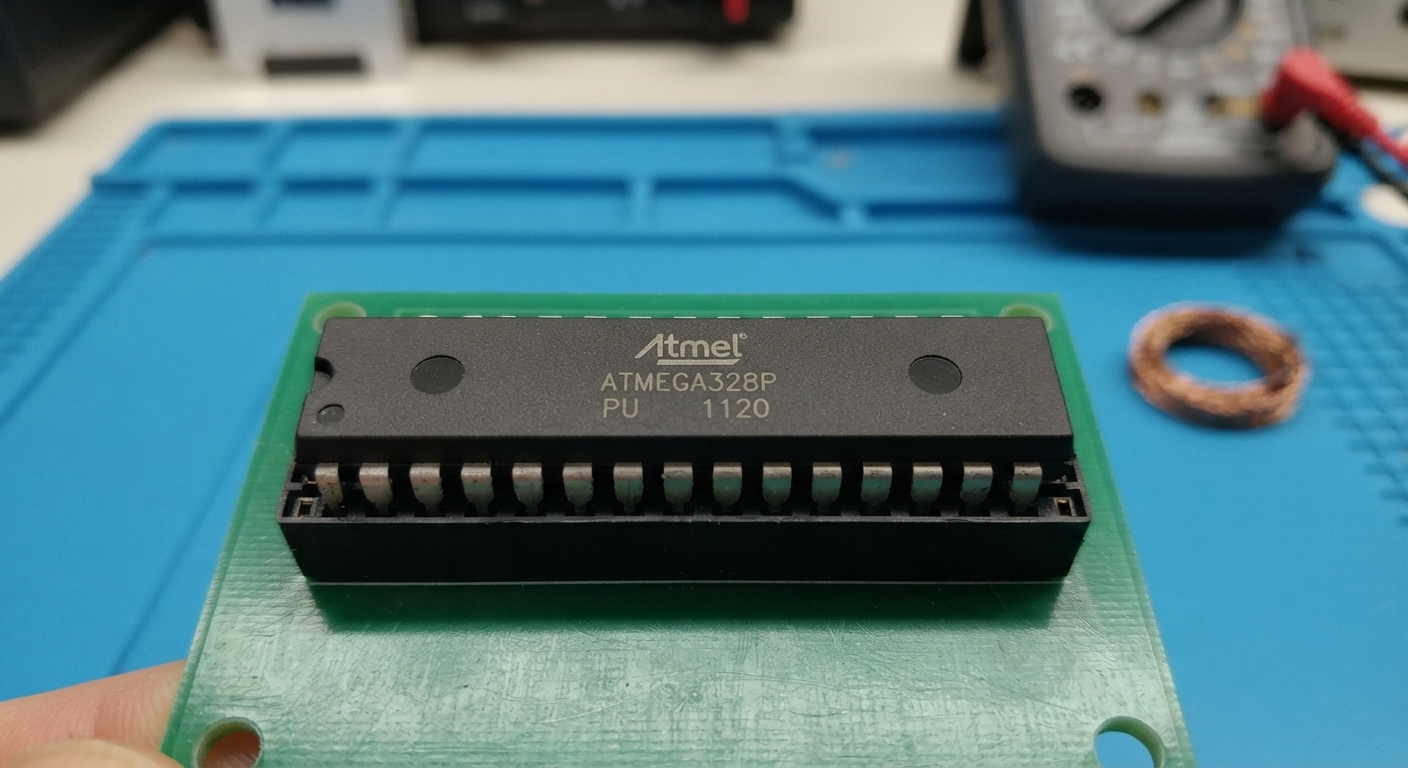
This makes the embedded software a critical part of the overall product, particularly when a system has been manufactured for many years. Unfortunately, original development projects and engineering archive files can become unavailable as companies change suppliers, designers leave, or legacy computers are retired. A customer may still possess a functioning ATMEGA-based board but no longer have its original source code, binary, or heximal programming file. Our “attack atmega mcu embeded firmware” service addresses this type of authorized engineering requirement by analyzing existing hardware and helping customers preserve valuable embedded software information.
Attack ATmega MCU encryption system by using focus ion beam technique which one of the most commonly used Microcontroller unlocking methods to cut off the security fuse bit and readout Embeded Firmware from microprocessor memory;
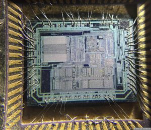
The opposite process to chip fabrication is called deprocessing. A standard CMOS chip has many layers. The deepest doping layers inside the substrate form the transistors. The gate oxide layer isolates the gate from the active area of the transistors. The polysilicon layer on top of it forms the gates and interconnections. The interlayer oxide isolates conducting layers.
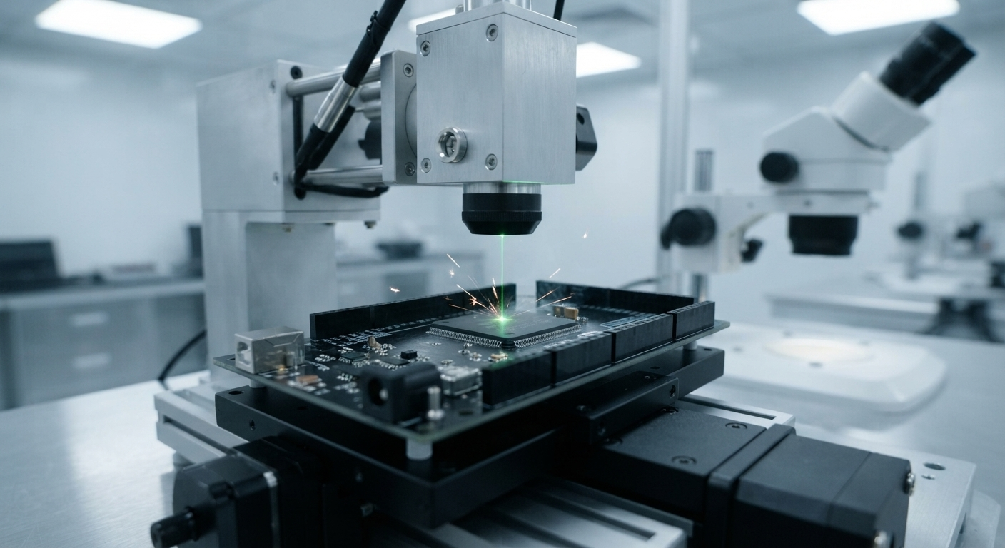
Our recovery methodology starts with a technical evaluation of the target atmega mcu, its PCB, available documentation, and the condition of its internal memory. Engineers assess whether useful firmware, binary, heximal, program, and configuration data can be recovered and what form the final engineering output can realistically take. Depending on the specific device and project requirements, laboratory analysis may include controlled semiconductor examination and carefully managed decapsulate procedures to investigate difficult internal structures. Recovered information can then be retrieved, organized, and decoded into practical file and archive formats for engineering assessment.
When customers describe a project as an attempt to attack, break, or hack an embedded device, the professional objective remains authorized recovery rather than unauthorized access. Devices may contain protective, protected, locked, secured, or encrypted configurations, and the feasibility of recovering their contents depends on the particular architecture and protection scheme. Where recovery is technically possible and properly authorized, the resulting firmware resources can support controlled clone evaluation, duplicate development, product maintenance, compatibility verification, and reconstruction of missing technical documentation. The recovered information may also help engineers understand the relationship between the application program, peripheral configuration, and hardware behavior.
Metal layers, usually made of aluminium (Al), form the signal wires, and they are connected with other layers through ‘via’ plugs (Al, W, Ti). Finally, a passivation layer made out of silicon oxide SiO2 or nitride Si3N4 protects the whole structure from moisture and air which could harm the die. In plastic packages the passivation layer is covered with a polymer layer, usually polyimide, to protect against sharp grains in the compound during the package formation.
An important part of the work is distinguishing a raw memory image from useful engineering information. A recovered binary does not automatically constitute the original source code, because compiled firmware normally contains machine instructions rather than the developer’s original comments, variable names, and project files. Engineers therefore analyze the recovered data together with the behavior of the original circuit. Communication interfaces, input/output functions, timing characteristics, peripheral activity, and system responses can provide valuable evidence for interpreting the firmware structure. This is particularly useful when a legacy product must be repaired or transferred to a new production environment.
Although the primary focus of this service is the ATMEGA platform, similar principles can apply to other microprocessor, microcontroller, and embedded architectures. The requested keyword dsp or texas instrument, for example, relates to a different class of processor technology, but the broader requirement for firmware preservation, documentation recovery, and lifecycle support is comparable. Depending on the project, the final package may include validated firmware images, organized binary or heximal files, reconstructed program documentation, memory information, and technical archive materials.

For manufacturers, maintenance providers, and authorized engineering teams, recovering ATMEGA firmware can provide significant practical benefits. It can reduce the cost of recreating an established product, preserve engineering knowledge, support discontinued equipment, and provide a foundation for future redesign. Instead of abandoning a proven electronic platform because its original software files have disappeared, an organization can investigate the existing mcu and determine what embedded resources remain available.
Recovered firmware, program information, and technical file records can help with replacement-board development, troubleshooting, product modernization, and migration to a newer microcontroller. By combining embedded-system expertise, memory analysis, firmware reconstruction, and semiconductor investigation, our service helps customers preserve valuable technology contained within existing ATMEGA hardware and extend the useful life of mature electronic products.
Microcontroller Break Categories
Microcontroller Break Categories
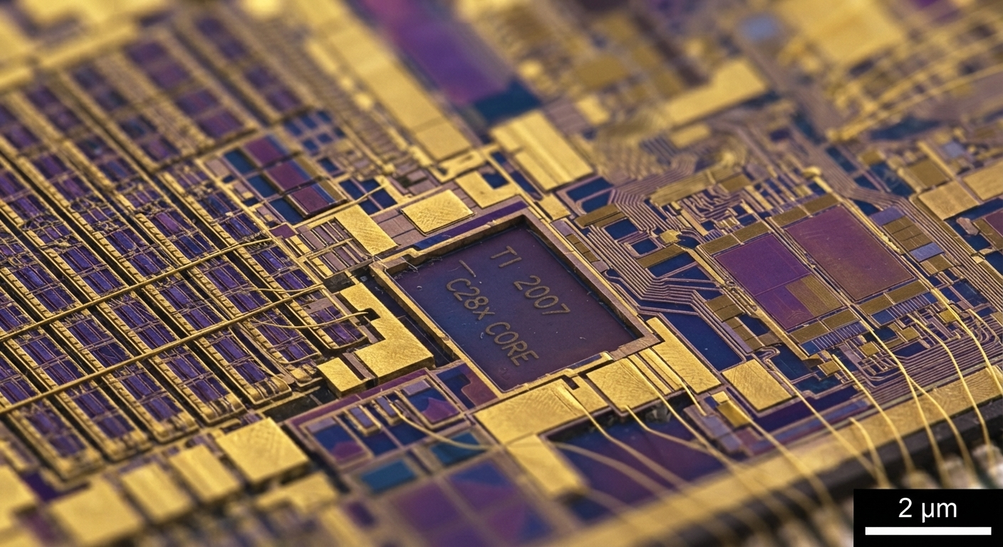
We can distinguish five major microcontroller break categories:
Microprobing techniques can be used to access the chip surface directly, so we can observe, manipulate, and interfere with the integrated circuit.
Reverse engineering is used to understand the inner structure of semiconductor chip and learn or emulate its functionality. It requires the use of the same technology available to semiconductor manufacturers and gives similar capabilities to the attacker.
Software microcontroller breaks use the normal communication interface of the processor and exploit security vulnerabilities found in the protocols, cryptographic algorithms, or their implementation.
microcontroller break
Eavesdropping techniques allows the microcontroller breaker to monitor, with high time resolution, the analog characteristics of supply and interface connections and any electromagnetic radiation by the processor during normal operation.
Fault generation techniques use abnormal environmental conditions to generate malfunctions in the processor that provide additional access.
All microprobing and reverse engineering techniques are invasive microcontroller breaks. They require hours or weeks in specialised laboratory and in the process they destroy the packaging.
The other three are non-invasive microcontroller breaks. The microcontroller breaked device is not physically harmed during these microcontroller breaks.
The last microcontroller break category could also be semi-invasive. It means that the access to the chip’s die is required but the microcontroller break is not penetrative and the fault is generated with intensive light pulse, radiation, local heating or other means.
Attack ATmega MCU Microcontroller Firmware
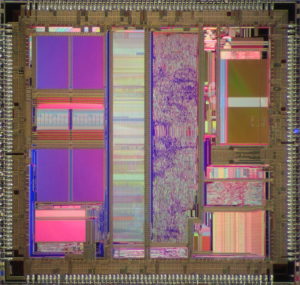
Attack ATmega MCU Microcontroller Firmware from flash memory and eeprom memory, then extract the source code from its memory and copy the firmware to new Microprocessor;
Attack ATmega MCU Microcontroller Firmware from flash memory and eeprom memory, then extract the source code from its memory and copy the firmware to new Microprocessor;
The same partial decapsulation technique can be used for smartcards as well (see below figure) although not all of them would maintain electrical integrity. Very often the chip has to be decapsulated completely and then bonded onto a chip carrier. Other methods used for opening the chip packages are described in the literature and only very few of them require expensive tools.
One interesting approach suggests using an acid resistant tape to prevent the acid reacting with unwanted parts. The chip is placed on a glass to prevent lead bending and then covered with acid resistant tape. The tape over the area to be etched is cut away and the whole package is then immersed in a chemical solution to etch away the plastic. This method is limited to QFP, SOP, BGA and other thin packages.
Attack ATmega IC Chip Microcontroller AVR Program
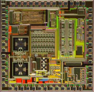
Attack ATmega IC Chip Microcontroller AVR and readout program and data from flash and eeprom memory, decrypt the firmware in the format of binary or heximal to un-encrypted status;
Attack ATmega IC Chip Microcontroller AVR and readout program and data from flash and eeprom memory, decrypt the firmware in the format of binary or heximal to un-encrypted status;
A very similar approach can be used for decapsulating chips from the rear side. The only obstacle is the copper plate under the chip die which reacts slowly with the fuming nitric acid. That could create problems if the automatic decapsulator is used because the surrounding plastic will be etched away before this copper plate and the chip leads are very likely to be damaged (Figure below).
However, access to the rear side of the die can be established without using chemical etching. The chip package can be milled down to the copper plate which is then removed mechanically. The residues of the glue used to attach the die to the plate can be removed with solvents or by scraping it off with a wooden toothpick stick.
Attack ATmega IC Embeded Firmware
Attack ATmega IC can help engineer to reset the status of ATmega Microcontroller from locked to unlocked one by crack MCU technique, then extract the ic code from program memory;
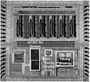
Attack ATmega IC can help engineer to reset the status of ATmega Microcontroller from locked to unlocked one by crack MCU technique, then extract the ic code from program memory;
For decapping chips in large quantities an automatic decapsulation system can be used, for example PA103 from Nippon Scientific. Very little skill and experience is required to operate it, and packages can be decapped easily even by unskilled workers.
Such systems cost over £10,000 and are bought by relatively large labs only. They also consume ten times more acid compared to the manual method, and their waste has to be disposed of in a proper way to avoid harm to the environment.
Attack DSP Chip Encrypt Code
Attack DSP Chip by chemical decapsulation, through which it will be able to get access to the databus of microcontroller memory and extract encrypted code from flash and eeprom memory;
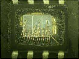
Attack DSP Chip by chemical decapsulation, through which it will be able to get access to the databus of microcontroller memory and extract encrypted code from flash and eeprom memory;
The acid residues can be removed from the etched plastic and from the chip surface by ultrasonic treatment. For that the chip is placed into a beaker with acetone and then put in an ultrasonic bath for 1–3 minutes. After washing the chip with acetone and drying it in an air jet, we have a clean and fully operational chip.
Attack DSP IC Chip Encrypted System
Attack DSP IC Chip program memory to extract encrypted data from MCU memory, disable the tamper resistance system by Microcontroller unlocking;
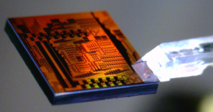
Attack DSP IC Chip program memory to extract encrypted data from MCU memory, disable the tamper resistance system by Microcontroller unlocking
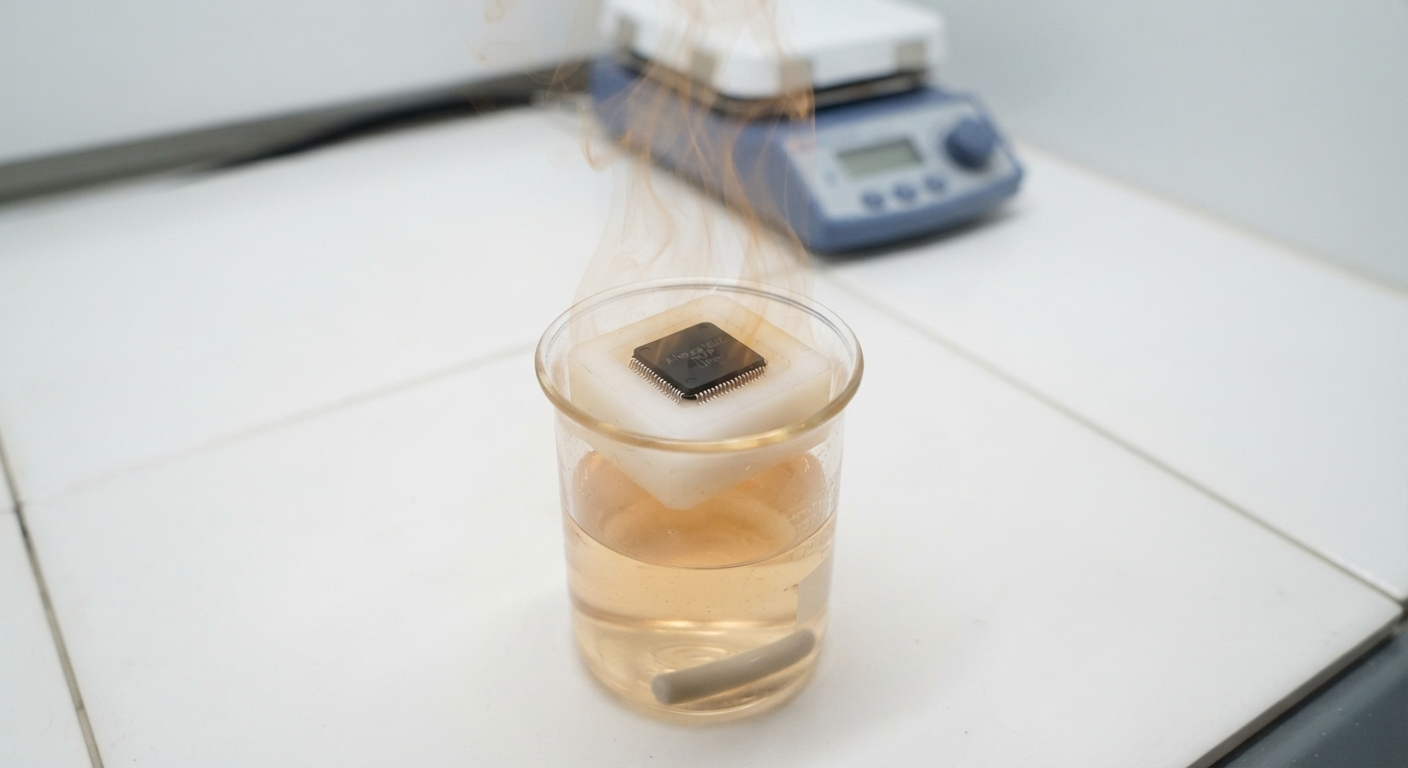
The acid is normally applied in small portions with a pipette into a pre-milled hole in a chip preheated to 50–70˚C (Figure 51). After 10–30 seconds the chip is sprayed with dry acetone from a washing bottle to remove the reaction products. This process has to be repeated several times until the die is sufficiently exposed. To speed up the process, the chip can be placed in a sand bath and the acid can be preheated in a glass beaker. see below picture: