 Flexible Printed Circuit Board Integration
 July 17th, 2012 |
 Author:
To achieve an optimal interconnect and packaging design, it is important to utilize flexible printed circuit board only when flexible printed circuit board best satisfies application and other needs.
Flexible printed circuit board is a good choice when the primary need is for flexible, conformal, thin, lightweight, etc. Flex is also a good choice for applications requiring comparatively high I/O density, low cost, or performance advantages that cannot be achieved in PCB constructions. Flexible printed circuit board can be utilized in many applications other than the aforementioned “good choices”; however, the user is strongly encouraged to consider cables, PCB, and other suitable interconnect technologies or else risk unnecessary design complexity, reliability risk, system connector challenges, higher cost, etc. As in conventional electrical design, interconnect must be partitioned according to product specifications including performance, reliability, cost, et al.
Interconnect partitioning, intentional or otherwise, can be found in the hierarchy of interconnects that is in almost any electronic system. For example, although personal computers include state-of-the-art semiconductors and their corresponding nanometer feature sizes, the power for those semiconductors is supplied through cables that are constructed using 18-gauge or larger conductors. Likewise, packaging designers need to partition the interconnect chain to satisfy system specifications, requirements, etc., using “just enough technology.”
The Flexible printed circuit board that interconnects the detector panel and signal processing electronics is a 2ML, 150-micron pitch design. One end of the Flexible printed circuit board is bonded to the panel; the other end is bonded, using ACF, to a multilayer PCB. Multiple ASICs (in bare die form) are attached, in a linear array, on the PCB; the ASICs are wirebonded to the PCB. The ASICs amplify and convert the analog signals produced by the detector panel and route those signals through a connector to a second flexible printed circuit board that connects to the system electronics. The second flexible printed circuit board, because of multiplexing of the digitized signals, requires fewer signal conductors; thus, it is a low-density 2ML flexible printed circuit board (signal plus shield layer).
The next logical step in packaging optimization for this type of electronic system would be the integration of the ASICs and ancillary electronics into the flexible printed circuit board. This integration step, if done properly, would replace the PCB with flexible printed circuit board, reduce the number of interconnects, and reduce detector panel manufacturing steps, without increasing the cost of the flex-PCB-flex system, as above.
Break IC PIC12F509 Eeprom
Break IC PIC12F509 Eeprom protection and extract hexiaml from MCU PIC12F509, reprogramme the firmware to new PIC12F509 microcontroller for cloning;
After generating a START condition, the bus master transmits a control byte consisting of a slave address and a Read/Write bit that indicates what type of operation is to be performed.
The slave address consists of a 4-bit device code (1010) followed by three don’t care bits. The last bit of the control byte determines the operation to be performed.
When set to a one a read operation is selected, and when set to a zero a write operation is selected. (Figure 7-5). The bus is monitored for its corresponding slave address all the time before recover chip pic12c508 software.
It generates an acknowledge bit if the slave address was true and it is not in a programming mode. Following the start signal from the master, the device code (4 bits), the don’t care bits (3 bits), and the R/W bit (which is a logic low) are placed onto the bus by the master transmitter.
This indicates to the addressed slave receiver that a byte with a word address will follow after it has generated an acknowledge bit during the ninth clock cycle. Therefore, the next byte transmitted by the master is the word address and will be written into the address pointer.
Only the lower four address bits are used by the device, and the upper four bits are don’t cares. The address byte is acknowledgeable and the master device will then transmit the data word to be written into the addressed memory location.
The memory acknowledges again and the master generates a stop condition. This initiates the internal write cycle, and during this time will not generate acknowledge signals. After a byte write command, the internal address counter will not be incremented and will point to the same address location that was just written.
If a stop bit is transmitted to the device at any point in the write command sequence before the entire sequence is complete, then the command will abort and no data will be written. If more than 8 data bits are transmitted before the stop bit is sent, then the device will clear the previously loaded byte and begin loading the data buffer again.
If more than one data byte is transmitted to the device and a stop bit is sent before a full eight data bits have been transmitted, then the write command will abort and no data will be written. The EEPROM memory employs a VCC threshold detector circuit which disables the internal erase/write logic if the VCC is below minimum VDD. Byte write operations must be preceded and immediately followed by a bus not busy bus cycle where both SDA and SCL are held high.
 Posted in Break IC |
 Tags: break protected ic binary, break protected ic code, break protected ic data, break protected ic eeprom, break protected ic file, break protected ic firmware, break protected ic flash, break protected ic heximal, break protected ic memory, break protected ic software |
 Comments Closed
Challenge of Flexible Circuit Board
The primary challenge in today’s flexible printed circuit board technology is its I/O capability, as determined by minimum feature sizes. For example, in single-metal-layer (1ML) flexible printed circuit, trace and space widths as small as 10-microns have been produced using commercial processes, materials, etc. Even finer features have been produced, a transfer lithography process comprised of 4-micron-pitch (one-micron trace, three-micron space), flexible circuit board configuration. Similarly, feature sizes in two-metal-layer (2ML) flexible circuit board, the lion’s share of commercial flexible circuit board production, have been reduced to twenty-five microns. But minimum trace and space geometries do not tell the entire story of I/O capability for flexible circuit board.
There are many questions to pose when assessing the capabilities of potential flexible circuit board suppliers; perhaps the most critical is, what are the supplier’s minimum via land pad dimensions? The dimensions of the via land pad highlight the alignment capability of the flexible circuit board supplier’s processes and dictate the minimum pitch of the flexible circuit board interconnect. Consequently, not all 2ML flexes with twenty-five micron features have equal interconnect density. Moreover, even though feature sizes are decreasing, I/O capability in flexible circuit board is not increasing or, at a minimum, is not increasing at the same rate.
Accordingly, second-level assembly continues to move closer and closer to the device. As witnessed in chip-sized and chip-scale packages, by adapting an existing technology to a novel configuration, the unmet needs for very fine pitch, high volumetric I/O packages effected the reduction in use or elimination of standard electronic packages. Plastic encapsulated lead frames and multilayer ceramic packages have been replaced by plastic encapsulated flex interconnected bare die or, in many cases, by bare die. Similarly, the increasing use of direct chip attach results, in part, from the inability of flex interconnect to meet the constant demand for higher pixel counts in displays. In this case, package interconnect by means of wirebonds with millimeters of length and flex interconnect of tens to hundreds of millimeters in length has been replaced by stud bumps (of tens of microns in diameter, produced using the same wirebonding equipment and materials) and the complete elimination of the flex interconnect. Electronic packaging technologists and applications engineers are currently developing similar system-based solutions and applications by revisions, enhancements, etc., to existing interconnect technologies in order to meet the never-ending demand for greater interconnect density and capability. However, even though its features continue to lag behind those of semiconductors, flexible circuit board has and always will play a significant role in the optimization of system design.
Decrypt Locked Chip PIC12F508 Firmware
Decrypt Locked Chip PIC12F508 Firmware from secured program memory and data memory, microcontroller PIC12F508 cracking will help to disable the protection and readout MCU PIC12F508 heximal.
The code for these functions is available on our website www.microchip.com. The code will be accessed by either including the source code FL51XINC.ASM or by linking FLASH5IX.ASM.
It is very important to check the return codes when using these calls, and retry the operation if unsuccessful. Unsuccessful return codes occur when the EE data memory is busy with the previous write, which can take up to 4 mS if copy chip pic16c73a program.
SDA is a bi-directional pin used to transfer addresses and data into and data out of the device. For normal data transfer SDA is allowed to change only during SCL low. Changes during SCL high are reserved for indicating the START and STOP conditions.
The EEPROM interface is a 2-wire bus protocol consisting of data (SDA) and a clock (SCL). Although these lines are mapped into the GPIO register, they are not accessible as external pins; only to the internal EEPROM peripheral after recover mcu pic16f74a binary.
SDA and SCL operation is also slightly different than GPO-GP5 as listed below. Namely, to avoid code overhead in modifying the TRIS register, both SDA and SCL are always outputs.
To decrypt data from the EEPROM peripheral requires outputting a ‘1’ on SDA placing it in high-Z state, where only the internal 100K pull-up is active on the SDA line.
This code must reside in the lower half of a page. The code achieves it’s small size without additional calls through the use of a sequencing table. The table is a list of procedures that must be called in order.
The table uses an ADDWF PCL,F instruction, effectively a computed goto, to sequence to the next procedure. However the ADDWF PCL,F instruction yields an 8 bit address after recover chip pic16c71 code,
The following bus protocol is to be used with the EEPROM data memory.
Data transfer may be initiated only when the bus is not busy.
During data transfer, the data line must remain stable whenever the clock line is HIGH. Changes in the data line while the clock line is HIGH will be interpreted as a period of the clock signal. There is one bit of data per clock pulse.
Each data transfer is initiated with a START condition and terminated with a STOP condition. The number of the data bytes transferred between the START and STOP conditions is determined by the master device and is theoretically unlimited if Decrypt locked Chip Firmware. A HIGH to LOW transition of the SDA line while the clock (SCL) is HIGH determines a START condition. All commands must be preceded by a START condition. A LOW to HIGH transition of the SDA line while the clock (SCL) is HIGH determines a STOP condition. All operations must be ended with a STOP condition.
Posted in Break IC |
Tags: decrypt locked chip bin, decrypt locked chip code, decrypt locked chip data, decrypt locked chip eeprom, decrypt locked chip file, decrypt locked chip firmware, decrypt locked chip hex, decrypt locked chip memory, decrypt locked chip program, decrypt locked chip software |
Comments Closed
System-Based Flexible PCB Applications
The demand for thin, lightweight, high-density interconnect continues unabated. Similarly, application strategies for satisfying the ever-changing and ever-growing demand for high-density interconnect continue to change. Since their inception, flexible PCB have evolved into a cornerstone technology of high-density interconnect. Flexible PCB has become a fundamental interconnect technology, from its first application in tape automated bonding (TAB) and corresponding simple, point-to-point configurations to the fine-pitch, multilayer designs that are commonplace in today’s mobile electronic products. However, the approaches in using flexible PCB to satisfy the demands of high-performance, highly reliable systems with high volumetric density I/O are still evolving.
Following a familiar path of technology development, the use of flexible PCB has changed from first-level to second-level interconnect applications; More recently, the role of flexible PCB has been expanded to include system-level interconnect. At each point in its changing role in applications, flexible PCB technology has been modified to meet the application demands. For example, to meet the demands of die-to-die interconnect, the single-layer, via-less, point-to-point circuits found in 1970s TAB packaging sprouted additional layers. The transformation to multilayer interconnect required the development of new features such as vias for interconnecting layers; new materials such as adhesives to bond dielectric and conductor layers; and new processes and equipment for manufacturing the resulting incarnation of flexible PCB. As device I/O increased beyond the capabilities of existing multilayer technology, the trace and space features of flexible PCB were reduced. Over the past twenty years, feature sizes in flexible PCB such as conductor geometry, via diameter, dielectric thickness, etc., have been improved significantly. These improvements positioned flexible PCB for its now-dominant position in portable consumer, display, and medical electronics interconnect applications.
As witnessed over the past ten years, the reduction in interconnect feature size has slowed. At the same time, device I/O counts have increased as semiconductor features have decreased, according to Moore’s Law. This disparity in interconnect and semiconductor feature size has created an interconnect “brick wall” that demonstrates the need for advancing the capabilities of interconnect systems. Semiconductor device minimum feature size (and rate of decrease in feature size) far exceeds the equivalent in flexible PCB and PCB Clone technologies. The corresponding gap in interconnect capability has and will limit advances in semiconductor applications until advances in volumetric I/O density, form factor, weight, flexibility, etc., are implemented in flexible PCB. In the meantime, flexible PCB must be utilized as an integral part of the interconnect system.
Although the complexity of electronic systems has increased over the past ten years, the challenges in interconnect systems have been minimized due to the functional partitioning of electronic systems into key subsystems: encoding/decoding ic, processing, display, and power.
Typically, flexible PCB is utilized for interconnection within a subsystem as well as for system interconnect.
Retrieve IC PIC16LF57 Program
Retrieve IC PIC16LF57 Program from flash memory and eeprom memory, change the MCU PIC16LF57 status by unlock microcontroller‘s fuse bit and make PIC16LF57 processor copy;
The program for these functions is available on our website www.microchip.com. The program will be accessed by either including the source program FL51XINC.ASM or by linking FLASH5IX.ASM.
It is very important to check the return programs when using these calls, and retry the operation if unsuccessful. Unsuccessful return programs occur when the EE data memory is busy with the previous write, which can take up to 4 mS if break IC PIC16F884 code.
SDA is a bi-directional pin used to transfer addresses and data into and data out of the device. For normal data transfer SDA is allowed to change only during SCL low.
Changes during SCL high are reserved for indicating the START and STOP conditions. The EEPROM interface is a 2-wire bus protocol consisting of data (SDA) and a clock (SCL). Although these lines are mapped into the GPIO register, they are not accessible as external pins; only to the internal EEPROM peripheral after break IC PIC16F72A binary.
SDA and SCL operation is also slightly different than GPO-GP5 as listed below. Namely, to avoid program overhead in modifying the TRIS register, both SDA and SCL are always outputs. To read data from the EEPROM peripheral requires outputting a ‘1’ on SDA placing it in high-Z state, where only the internal 100K pull-up is active on the SDA line.
This program must reside in the lower half of a page. The program achieves it’s small size without additional calls through the use of a sequencing table. The table is a list of procedures that must be called in order. The table uses an ADDWF PCL,F instruction, effectively a computed goto, to sequence to the next procedure after Reverse eng microcontroller pic16c65b eeprom.
Posted in Recover Chip |
Tags: retrieve secured ic binary, retrieve secured ic code, retrieve secured ic configuration, retrieve secured ic data, retrieve secured ic eeprom, retrieve secured ic file, retrieve secured ic firmware, retrieve secured ic heximal, retrieve secured ic memory, retrieve secured ic program, retrieve secured ic software |
Comments Closed
Flexural Endurance Test after Flexible Circuit Manufacturing
GE Research has developed a version of the flexural endurance test based on the IPC standard. Added features to the tester include:
Automated resistivity monitor with threshold
Multiple circuit load (4–up)
Pogo-pin quick connection
Variable-speed motor
Fine-pitch pattern (25mm traces)
Automated data logger
GE Research has also developed a number of TEG monitor cells that are assembled as blocks in a library for use on multiple platforms (RF, DC, analog, PWB, thin core, silicon, etc). The TEG blocks can be assembled in the field area of the panel to aid in process monitoring, second-level assembly, and reliability screening. GE Research has also developed specific tooling to aid in the characterization of thin-core flexible interconnect materials.
Examples of the tools include elongation test stands, flexural endurance systems, and automated electrical testing platforms. The TEG monitors are regularly used in healthcare, military, and commercial flex circuit Manufacturing. These monitors are often used as screening tools for vendor capability demonstrations. Electrical performance, and the corresponding electrical functional testing, is also a critical aspect in flexible printed circuits. Procedures for functional testing are application–specific, but generally, basic function including impedance characterization is tested. Often, users overlook characterization of surface isolation resistance because its adverse impact on electrical performance in low-signal amplitude (microvolts, microamps) applications is not considered or because of the difficulties in obtaining valid data at low-signal amplitudes, especially in the environments required for isolation resistance testing.
Posted in PCB Manufacture |
Tags: flex circuit manufacturing, flexible circuit manufacturing |
Comments Closed
Break IC PIC16LF54 Protection
Break IC PIC16LF54 Protection and extract code from MCU PIC16LF54, crack Microcontroller PIC16LF54 fuse bit and decapsulate package;
When a prescaler is used, the external clock input is divided by the asynchronous ripple counter-type prescaler so that the prescaler output is symmetrical.
For the external clock to meet the sampling requirement, the ripple counter must be taken into account. Therefore, it is necessary for T0CKI to have a period of at least 4TOSC (and a small RC delay of 40 ns) divided by the prescaler value if recover chip pic16hv785 hex.
The only requirement on T0CKI high and low time is that they do not violate the minimum pulse width requirement of 10 ns. Refer to parameters 40, 41 and 42 in the electrical specification of the desired device.
Since the prescaler output is synchronized with the internal clocks, there is a small delay from the time the external clock edge occurs to the time the Timer0 module is actually incremented before recover chip pic16c621 program.
Figure 6-4 shows the delay from the external clock edge to the timer incrementing. If the option register is set to read TIMER0 from the pin, the port is forced to an input regardless of the TRIS register setting.
The prescaler assignment is fully under software control (i.e., it can be changed “on the fly” during program execution). To avoid an unintended device RESET, the following instruction sequence (Example 6-1) must be executed when changing the prescaler assignment from Timer0 to the WDT when Break IC pic16f621a program.
The PIC16LF54 each have 16 bytes of EEPROM data memory. The EEPROM memory has an endurance of 1,000,000 erase/write cycles and a data retention of greater than 40 years.
The EEPROM data memory supports a bi-directional 2-wire bus and data transmission protocol. These two-wires are serial data (SDA) and serial clock (SCL), that are mapped to bit6 and bit7, respectively, of the GPIO register (SFR 06h) after recover mcu pic16c622a software.
Unlike the GP0-GP5 that are connected to the I/O pins, SDA and SCL are only connected to the internal EEPROM peripheral. For most applications, all that is required is calls to the following functions;
Decode Locked MCU PIC16F57 Heximal Data
Decode Locked MCU PIC16F57 Heximal Data from eeprom memory, unlock microcontroller PIC16F57 security fuse bit and extract firmware out from microprocessor memory;
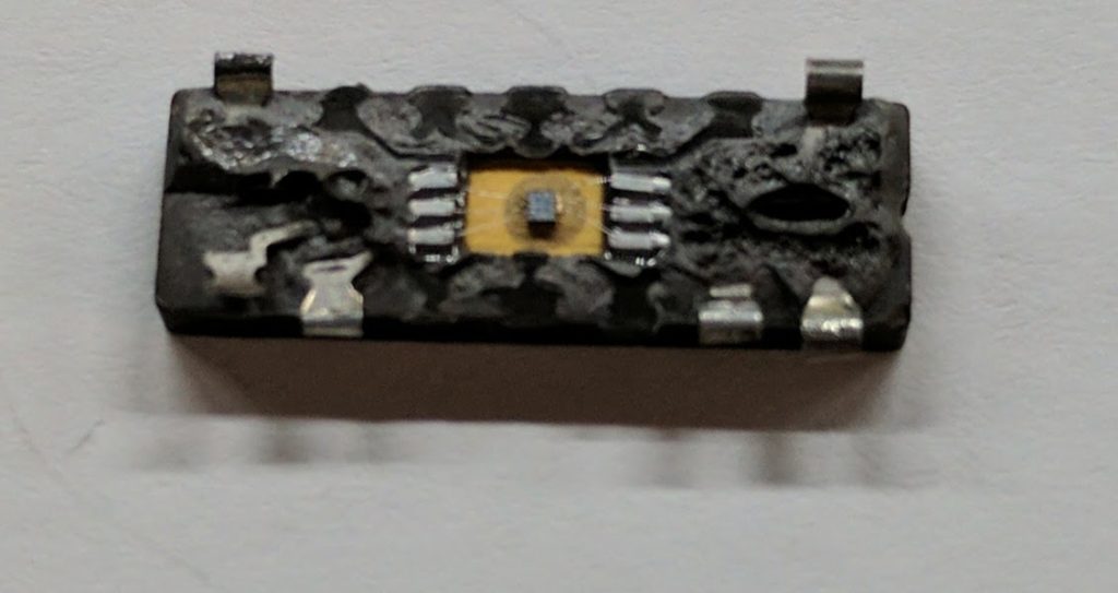
The Timer0 module has the following features:
8-bit timer/counter register, TMR0
– Readable and writable
8-bit heximal data programmable prescaler
Internal or external clock select
– Edge select for external clock
Figure 6-1 is a simplified block diagram of the Timer0 module.
Timer mode is selected by clearing the T0CS bit (OPTION<5>). In timer mode, the Timer0 module will increment every instruction cycle (without prescaler) if break ic pic16f917 hex.
If TMR0 register is written, the increment is inhibited for the following two instruction cycles (Figure 6-2 and Figure 6-3). The user can work around this by writing an adjusted value to the TMR0 register.
Counter mode is selected by setting the T0CS bit (OPTION<5>). In this mode, Timer0 will increment either on every rising or falling edge of pin T0CKI.
The T0SE bit (OPTION<4>) determines the source edge. Clearing the T0SE bit selects the rising edge. Restrictions on the external clock input are discussed in detail in Section 6.1.
The prescaler may be used by either the Timer0 module or the Watchdog Timer, but not both. The prescaler assignment is controlled in heximal data by the control bit PSA (OPTION<3>) after recover mcu pic16f72 code.
Clearing the PSA bit will assign the prescaler to Timer0. The prescaler is not readable or writable. When the prescaler is assigned to the Timer0 module, prescale values of 1:2, 1:4,…, 1:256 are selectable. Section 6.2 details the operation of the prescaler.
A summary of registers associated with the Timer0 When an external clock input is used for Timer0, it must meet certain requirements. The external clock requirement is due to internal phase clock (TOSC) synchronization when recover mcu pic16f77 eeprom.
Also, there is a delay in the actual incrementing of Timer0 after synchronization. When no prescaler is used, the external clock input is the same as the prescaler output.
The synchronization of T0CKI with the internal phase clocks is accomplished by sampling the prescaler output on the Q2 and Q4 cycles of the internal phase clocks. Therefore, it is necessary for T0CKI to be high for at least 2TOSC (and a small RC delay of 20 ns) and low for at least 2TOSC (and a small RC delay of 20 ns). Refer to the electrical specification of the desired device.
Posted in Recover Chip |
Tags: decode locked mcu binary, decode locked mcu bits, decode locked mcu code, decode locked mcu data, decode locked mcu eeprom, decode locked mcu file, decode locked mcu firmware, decode locked mcu heximal, decode locked mcu memory, decode locked mcu program, decode locked mcu software |
Comments Closed
Process Challenges and System Applications in Flex Circuit Manufacturing
The use of flexible printed circuits has become prevalent in diagnostic imaging systems; in particular, the flex shown in Figure 4 is utilized in an ultrasound probe. The circuit shown has features of 4Mm-thick copper, 25Mm-thick polyimide, conductor pitch of 50Mm, and 25Mm-diameter laser-drilled vias.
Test Element Groups (TEGs) or process monitor coupons are critical components in the fabrication of reliable, high-quality flexible interconnect. TEGs are routinely used for standard process control (SPC), certification of compliance (COC), and reliability or qualification testing. A number of standards can be used for interconnect compliance, such as IPC, JDEC, ASTM, etc. TEGs can be utilized as in-process monitors, for post-fabrication validation, and as reliability screening coupons.
In-process monitoring examples include resistivity or Kelvin test structures to insure metal thickness after plating operations. Four-point probe resistivity measurements can be performed, prior to pattern and etch operations, to measure uniformity of metal deposits. Other in-process coupon examples include lithographic resolution structures (critical dimension measurement vehicles), impedance coupons, elongation/ductility coupons, flexural endurance coupons, and via interconnect strings. Via string coupons allow the manufacturer to test an array of vias (200-500) on the device panel for a measure of via integrity during and after flex circuit manufacturing. Via integrity can be measured by passing current through the via structure to insure that sidewall metal coverage is adequate for the circuit operation environment. The via string can combine all metal layers and metal layer pairs to aid in troubleshooting process fabrication issues (via drilling, via cleaning, via metallization). This coupon allows for circuit troubleshooting and, if performed in-process, can save process time and costs by identifying issues early in a process cycle. Specific via string designs allow for accurate measurements of metal contact resistance.