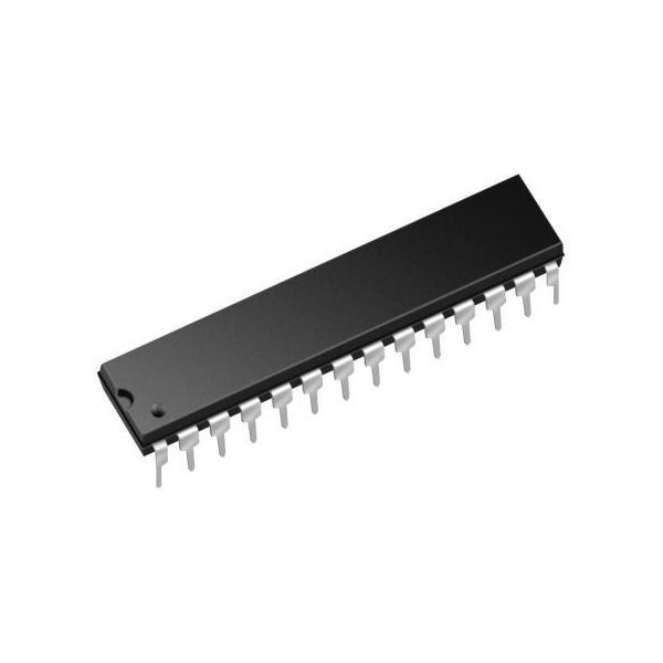
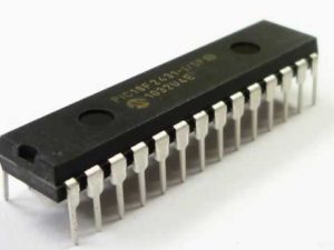
 Break PIC18F2510 Microcontroller Flash Memory
Break PIC18F2510 microcontroller flash memory protection and extract embedded firmware from secured PIC18F2510 Microchip MCU flash binary file memory and eeprom heximal data memory, copy source code to new locked microprocessor PIC18F2510;
break PIC18F2510 microcontroller flash memory protection and extract embedded firmware from secured PIC18F2510 Microchip MCU flash binary file memory and eeprom heximal data memory, copy source code to new locked microprocessor PIC18F2510;
A Phase Locked Loop (PLL) circuit is provided as an option for users who wish to use a lower frequency oscillator circuit which can be used for Break PIC18F2510 Microcontroller Flash Memory, or to clock the device up to its highest rated frequency from a crystal oscillator. This may be useful for customers who are concerned with EMI due to high-frequency crystals of Protected Winbond Microprocessor W78E65 Reverse Engineering, or users who require higher clock speeds from an internal oscillator.
Romper la protección de la memoria flash del microcontrolador PIC18F2510 y extraer el firmware integrado de la memoria de archivo binario flash MCU Microchip PIC18F2510 protegida y la memoria de datos hexagonales EEPROM, copiar el código fuente al nuevo microprocesador PIC18F2510 bloqueado;
The HSPLL mode makes use of the HS mode oscillator for frequencies up to 10 MHz. A PLL then multiplies the oscillator output frequency by 4 to produce an internal clock frequency up to 40 MHz. The PLLEN bit is not available in this oscillator mode after Winbond MCU W78E365 Heximal Data Restoration. The PLL is only available to the crystal oscillator when the FOSC3:FOSC0 Configuration bits are programmed for HSPLL mode (= 0110).
Break PIC18F2510 Microcontroller Flash Memory
The PLL is also available to the internal oscillator block when the INTOSC is configured as the primary clock source. In this configuration, the PLL is enabled in soft- ware and generates a clock output of up to 32 MHz. The operation of INTOSC with the PLL is described in Section 2.6.4 “PLL in INTOSC Modes” after Nuvoton Microcomputer W78E51B Encrypted Heximal Recovery.
The PIC18F2510 devices include an internal oscillator block which generates two different clock signals; either can be used as the microcontroller’s clock source. This may eliminate the need for external oscillator circuits on the OSC1 and/or OSC2 pins.
The main output (INTOSC) is an 8 MHz clock source, which can be used to directly drive the device clock. It also drives a postscaler, which can provide a range of clock frequencies from 31 kHz to 4 MHz. The INTOSC output is enabled when a clock frequency from 125 kHz to 8 MHz is selected, and can provide 31 kHz if required by Attack Nutovon Microcontroller W77E52 Flash Memory.
взломать защиту флэш-памяти микроконтроллера PIC18F2510 и извлечь встроенную прошивку из защищенной двоичной файловой флэш-памяти микроконтроллера PIC18F2510 Microchip и шестнадцатеричной памяти данных EEPROM, скопировать исходный код в новый заблокированный микропроцессор PIC18F2510;
The other clock source is the internal RC oscillator (INTRC) which provides a nominal 31 kHz output. INTRC is enabled if it is selected as the device clock source; it is also enabled automatically when any of the following are enabled:
• Power-up Timer
• Fail-Safe Clock Monitor
• Watchdog Timer
These features are discussed in greater detail in Section 23.0 “Special Features of the CPU” after the process of Crack MCU Eeprom. The clock source frequency (INTOSC direct, INTRC direct or INTOSC postscaler) is selected by configuring the IRCF bits of the OSCCON register on Break PIC18F2510 Microcontroller Flash Memory. Additionally, the 31 kHz clock can be provided by either the INTOSC, or INTRC clock sources, depending on the INTSRC bit (OSCTUNE<7>).
PIC18F2510 마이크로컨트롤러 플래시 메모리 보호를 해제하고 보안된 PIC18F2510 마이크로칩 MCU 플래시 바이너리 파일 메모리와 EEPROM 16진수 데이터 메모리에서 임베디드 펌웨어를 추출하고, 소스 코드를 새로운 잠긴 마이크로프로세서 PIC18F2510에 복사합니다.PIC18F2510 마이크로컨트롤러 플래시 메모리 보호를 해제하고 보안된 PIC18F2510 마이크로칩 MCU 플래시 바이너리 파일 메모리와 EEPROM 16진수 데이터 메모리에서 임베디드 펌웨어를 추출하고, 소스 코드를 새로운 잠긴 마이크로프로세서 PIC18F2510에 복사합니다.
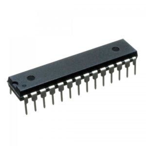
Copy PIC18F2480 MCU Locked Heximal
Copy PIC18F2480 Microchip MCU locked heximal out from secured microcontroller PIC18F2480 flash program memory and eeprom data memory needs to unlock protective PIC18F2480 microprocessor’s fuse bit, read embedded firmware out of binary file or heximal source code;
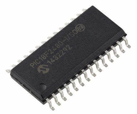
copy PIC18F2480 Microchip MCU locked heximal out from secured microcontroller PIC18F2480 flash program memory and eeprom data memory needs to unlock protective PIC18F2480 microprocessor’s fuse bit, read embedded firmware out of binary file or heximal source code;
Using the internal oscillator as the clock source eliminates the need for up to two external oscillator pins when Crack MCU Firmware, which can then be used for digital I/O and Copy PIC18F2480 MCU Locked Heximal. Two distinct configurations are available:
- In INTIO1 mode, the OSC2 pin outputs FOSC/4, while OSC1 functions as RA7 for digital input and output.
- In INTIO2 mode, OSC1 functions as RA7 and OSC2 functions as RA6, both for digital input and output.

copiar PIC18F2480 Microchip MCU bloqueado heximal de la memoria de programa flash PIC18F2480 del microcontrolador protegido y la memoria de datos EEPROM necesita desbloquear el bit fusible del microprocesador PIC18F2480 protector, leer el firmware incorporado del archivo binario o código fuente heximal;
The internal oscillator block is calibrated at the factory to produce an INTOSC output frequency of 8.0 MHz when Recover Atmel AVR Controller ATmega48V Firmware.
The INTRC oscillator operates independently of the INTOSC source. Any changes in INTOSC across voltage and temperature are not necessarily reflected by changes in INTRC and vice versa.
Copy PIC18F2480 MCU Locked Heximal
The internal oscillator’s output has been calibrated at the factory but can be adjusted in the user’s applica- tion. This is done by writing to the OSCTUNE register from Break Atmel AVR MCU ATmega8535L Heximal.
When the OSCTUNE register is modified, the INTOSC frequency will begin shifting to the new frequency. The INTOSC clock will stabilize within 1 ms. Code execu- tion continues during this shift after Break IC ATmega88V Internal Flash. There is no indication that the shift has occurred.
скопируйте заблокированный шестнадцатеричный код микроконтроллера PIC18F2480 из защищенного микроконтроллера. Необходимо разблокировать защитный бит предохранителя микропроцессора PIC18F2480 во флэш-памяти программ и памяти данных EEPROM, считать встроенную прошивку из двоичного файла или шестнадцатеричного исходного кода;
The OSCTUNE register also implements the INTSRC and PLLEN bits, which control certain features of the internal oscillator block. The INTSRC bit allows users to select which internal oscillator provides the clock source when the 31 kHz frequency option is selected when Restore Microprocessor Program Most Important Two Steps. This is covered in greater detail in Section 2.7.1 “Oscillator Control Register”. The PLLEN bit controls the operation of the frequency multiplier, PLL, in Internal Oscillator modes.
PIC18F2480 마이크로칩 MCU를 보안 마이크로컨트롤러 PIC18F2480 플래시 프로그램 메모리와 EEPROM 데이터 메모리에서 잠긴 16진수를 복사하여 보호 PIC18F2480 마이크로프로세서의 퓨즈 비트를 잠금 해제하고, 이진 파일이나 16진수 소스 코드에서 임베디드 펌웨어를 읽어야 합니다.
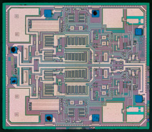
Losted PIC18F2458 Microcontroller Embedded Code Restoration
Losted PIC18F2458 microcontroller embedded code restoration is a process to recover binary file or heximal data from PIC18F2458 protective MICROCHIP MCU flash memory and eeprom memory, through PIC18F2458 microprocessor fuse bit unlocking technique;
losted PIC18F2458 microcontroller embedded code restoration is a process to recover binary file or heximal data from PIC18F2458 protective MICROCHIP MCU flash memory and eeprom memory, through PIC18F2458 microprocessor fuse bit unlock technique;
Without the back-up embedded firmware from microcontrollers sometimes could become the disaster for a company which try to rescue the obselete or not-produce-anymore devices, through our techniques, Losted PIC18F2458 Microcontroller Embedded Code Restoration process will help you get the firmware back from original PIC18F2458:
The HSPLL mode makes use of the HS mode oscillator for frequencies up to 10 MHz. A PLL then multiplies the oscillator output frequency by 4 to produce an internal clock frequency up to 40 MHz. The PLLEN bit is not available in this oscillator mode before Microchip PIC18F2520 Embedded Firmware Extraction.
Восстановление встроенного кода потерянного микроконтроллера PIC18F2458 представляет собой процесс восстановления двоичного файла или шестнадцатеричных данных из защитной флэш-памяти микроконтроллера MICROCHIP PIC18F2458 и памяти EEPROM с помощью техники разблокировки бита предохранителя микропроцессора PIC18F2458;
The PLL is only available to the crystal oscillator when the FOSC3:FOSC0 Configuration bits are programmed for HSPLL mode (= 0110).
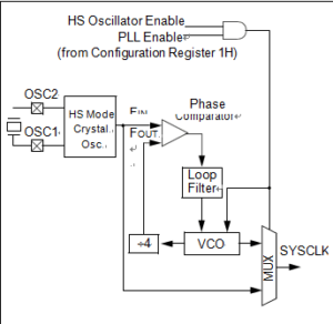
PLL BLOCK DIAGRAM
The PLL is also available to the internal oscillator block when the INTOSC is configured as the primary clock source from Microchip MCU PIC16F870 Heximal Code Restoration. In this configuration, the PLL is enabled in soft- ware and generates a clock output of up to 32 MHz.
The PIC18LF2458 devices include an internal oscillator block which generates two different clock signals; either can be used as the micro- controller’s clock source. This may eliminate the need for external oscillator circuits on the OSC1 and/or OSC2 pins in order to Recover Freescale MCU MC9S12XDG128 Memory Program.
kaybolan PIC18F2458 mikrodenetleyici gömülü kod restorasyonu, PIC18F2458 koruyucu MICROCHIP MCU flaş belleğinden ve eeprom belleğinden, PIC18F2458 mikroişlemci sigorta biti kilit açma tekniği aracılığıyla ikili dosya veya onaltılık verileri kurtarmak için bir işlemdir;
The main output (INTOSC) is an 8 MHz clock source, which can be used to directly drive the device clock. It also drives a postscaler, which can provide a range of clock frequencies from 31 kHz to 4 MHz. The INTOSC output is enabled when a clock frequency from 125 kHz to 8 MHz is selected, and can provide 31 kHz if required.
Losted PIC18F2458 Microcontroller Embedded Code Restoration
The other clock source is the internal RC oscillator (INTRC) which provides a nominal 31 kHz output after Reverse Engineering Microchip PIC16F1913 Memory. INTRC is enabled if it is selected as the device clock source; it is also enabled automatically when any of the following are enabled:
• Power-up Timer
• Fail-Safe Clock Monitor
• Watchdog Timer
These features are discussed in greater detail in Section 23.0 “Special Features of the CPU”.
The clock source frequency (INTOSC direct, INTRC direct or INTOSC postscaler) is selected by configuring the IRCF bits of the OSCCON register before Unlock Microcontroller Flash. Additionally, the 31 kHz clock can be provided by either the INTOSC, or INTRC clock sources, depending on the INTSRC bit (OSCTUNE<7>).
استعادة الكود المضمن في متحكم PIC18F2458 المفقود هي عملية لاستعادة ملف ثنائي أو بيانات سداسية من ذاكرة فلاش MCU الواقية PIC18F2458 وذاكرة EEPROM، من خلال تقنية فتح بت الصمامات للمعالج الدقيق PIC18F2458؛
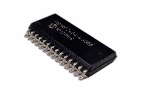
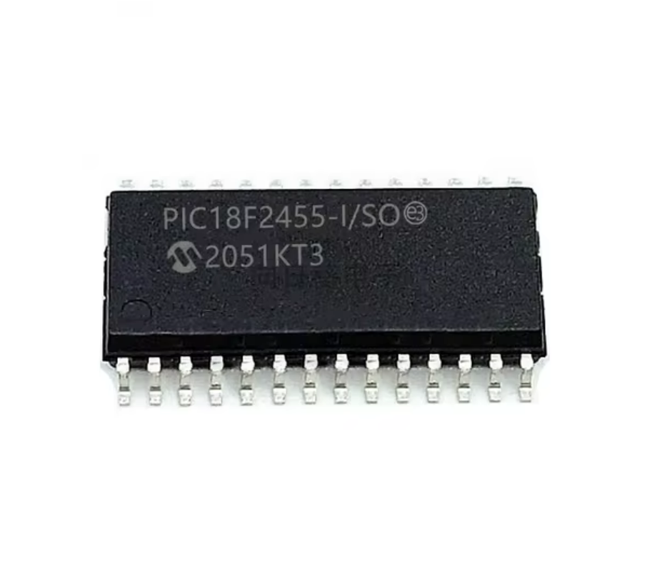
Recover Microchip PIC18F2455 Memory Program
Recover Microchip MCU PIC18F2455 memory program starts from crack encrypted microcontroller PIC18F2455 tamper resistance and then readout embedded firmware from locked microprocessor PIC18F2455 in the format of binary data or heximal file;
recover Microchip MCU PIC18F2455 memory program starts from crack encrypted microcontroller PIC18F2455 tamper resistance and then readout embedded firmware from locked microprocessor PIC18F2455 in the format of binary data or heximal file;
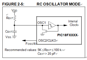
As one of the most important components to Recover Microchip PIC18F2455 Memory Program, for timing insensitive applications, the “RC” and “RCIO” device options offer additional cost savings. The actual oscillator frequency is a function of several factors:
• supply voltage
• values of the external resistor (REXT) and capacitor (CEXT)
• operating temperature
يبدأ برنامج استعادة ذاكرة Microchip MCU PIC18F2455 من كسر مقاومة العبث بالميكروكنترولر المشفر PIC18F2455 ثم قراءة البرامج الثابتة المضمنة من المعالج الدقيق المقفل PIC18F2455 بتنسيق بيانات ثنائية أو ملف سداسي عشري؛
Given the same device, operating voltage and temperature and component values, there will also be unit-to-unit frequency variations before Recover PIC MCU Microchip PIC16LF506 Firmware. These are due to factors such as:
• normal manufacturing variation
• difference in lead frame capacitance between package types (especially for low CEXT values)
• variations within the tolerance of limits of REXT and CEXT
Программа восстановления памяти микроконтроллера Microchip PIC18F2455 запускается с взломанного зашифрованного микроконтроллера PIC18F2455, защищенного от несанкционированного доступа, а затем считывает встроенную прошивку с заблокированного микропроцессора PIC18F2455 в формате двоичных данных или шестнадцатеричного файла;
In the RC Oscillator mode, the oscillator frequency divided by 4 is available on the OSC2 pin when Decrypt Microchip PIC18F2321 MCU Heximal File. This signal may be used for test purposes or to synchronize other logic after Recover PIC MCU Microchip 12F510 Firmware. Below Figure shows how the R/C combination is connected.
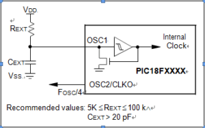
RC Oscillator Mode
The RCIO Oscillator mode (below Figure) functions like the RC mode, except that the OSC2 pin becomes an additional general purpose I/O pin. The I/O pin becomes bit 6 of PORTA (RA6).
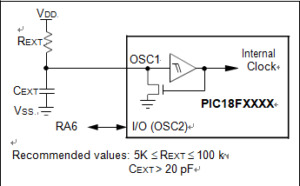
RCIO OSCILLATOR MODE in Recover Microchip PIC18F2455 Memory Program
A Phase Locked Loop (PLL) circuit is provided as an option for users who wish to use a lower frequency oscillator circuit, or to clock the device up to its highest rated frequency from a crystal oscillator after Copy Encrypted Microchip PIC18F2330 Heximal. This may be useful for customers who are concerned with EMI due to high-frequency crystals, or users who require higher clock speeds from an internal oscillator if the Microcontroller unlocking is completed.
Microchip MCU PIC18F2455 bellek programını kurtarma, şifrelenmiş mikrodenetleyici PIC18F2455 kurcalamaya dayanıklı kırılmadan başlar ve ardından kilitli mikroişlemci PIC18F2455’ten gömülü aygıt yazılımını ikili veri veya onaltılık dosya biçiminde okur;
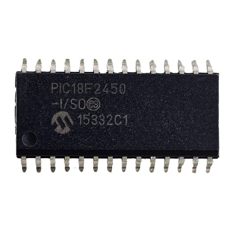
Break PIC18F2450 Microcontroller Locked Heximal
Break PIC18F2450 microcontroller locked heximal is a process start from decrypt secured microprocessor PIC18F2450 fuse bit to recover binary data or heximal file from MICROCHIP PIC18F2450 protective MCU flash program memory and eeprom code memory;
break PIC18F2450 microcontroller locked heximal is a process start from decrypt secured microprocessor PIC18F2450 fuse bit to recover binary data or heximal file from MICROCHIP PIC18F2450 protective MCU flash program memory and eeprom code memory;
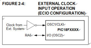
The EC and ECIO Oscillator modes require an external clock source to be connected to the OSC1 pin. There is no oscillator start-up time required after a Power-on Reset or after Break PIC18F2450 Microcontroller Locked Heximal. In the EC Oscillator mode, the oscillator frequency divided by 4 is available on the OSC2 pin. This signal may be used for test purposes or to synchronize other logic. Below Figure shows the pin connections for the EC Oscillator mode.
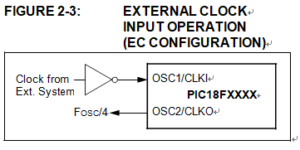
The ECIO Oscillator mode functions like the EC mode, except that the OSC2 pin becomes an additional general purpose I/O pin when Clone IC program. The I/O pin becomes bit 6 of PORTA (RA6). Figure 2-4 shows the pin connections for the ECIO Oscillator mode.
شکستن هگزیمال قفل شده میکروکنترلر PIC18F2450 فرآیندی است که از رمزگشایی ریزپردازنده ایمن بیت فیوز PIC18F2450 برای بازیابی اطلاعات باینری یا فایل هگزیمال از حافظه برنامه فلش محافظ MCU MICROCHIP PIC18F2450 و حافظه کد eeprom شروع می شود.
For timing insensitive applications, the “RC” and “RCIO” device options offer additional cost savings. The actual oscillator frequency is a function of several factors:
- supply voltage
- values of the external resistor (REXT) and capacitor (CEXT)
- operating temperature
Break PIC18F2450 Microcontroller Locked Heximal
Given the same device, operating voltage and temperature and component values, there will also be unit-to-unit frequency variations. These are due to factors such as:
PIC18F2450 माइक्रोकंट्रोलर लॉक हेक्सिमल को तोड़ना एक प्रक्रिया है जो डिक्रिप्ट सुरक्षित माइक्रोप्रोसेसर PIC18F2450 फ्यूज बिट से शुरू होती है, जो माइक्रोचिप PIC18F2450 सुरक्षात्मक MCU फ्लैश प्रोग्राम मेमोरी और ईप्रोम कोड मेमोरी से बाइनरी डेटा या हेक्सिमल फ़ाइल को पुनर्प्राप्त करती है;
- normal manufacturing variation
- difference in lead frame capacitance between package types (especially for low CEXT values)
- variations within the tolerance of limits of REXT and CEXT
In the RC Oscillator mode, the oscillator frequency divided by 4 is available on the OSC2 pin. This signal may be used for test purposes or to synchronize other logic. Figure 2-5 shows how the R/C combination is connected.
Взлом заблокированного шестнадцатеричного кода микроконтроллера PIC18F2450 — это процесс, начинающийся с расшифровки защищенного бита предохранителя микропроцессора PIC18F2450 для восстановления двоичных данных или шестнадцатеричного файла из программной флэш-памяти защитного микроконтроллера MICROCHIP PIC18F2450 и памяти кодов EEPROM;
Microcontroller PIC18F2439 Code Reverse Engineering
Microcontroller PIC18F2439 Code Reverse Engineering can help designer to copy source code from original Microchip locked MCU PIC18F2439 in the format of binary file or heximal data through unlock secured microprocessor PIC18F2439 fuse bit and readout embedded firmware from flash program memory and eeprom software memory;
microcontroller PIC18F2439 code reverse engineering can help designer to copy source code from original Microchip locked MCU PIC18F2439 in the format of binary file or heximal data through unlock secured microprocessor PIC18F2439 fuse bit and readout embedded firmware from flash program memory and eeprom software memory;
PIC18LF2439 devices can be operated in ten different oscillator modes when Clone IC flash. The user can program the Configuration bits which can be obtained in the process of Microcontroller PIC18F2439 Code Reverse Engineering, FOSC3:FOSC0, in Configuration Register 1H to select one of these ten modes:
1. LP Low-Power Crystal
2. XT Crystal/Resonator
3. HS High-Speed Crystal/Resonator
4. HSPLL High-Speed Crystal/Resonator with PLL Enabled
5. RC External Resistor/Capacitor with FOSC/4 Output on RA6
6. RCIO External Resistor/Capacitor with I/O on RA6
7. INTIO1 Internal Oscillator with FOSC/4 Output on RA6 and I/O on RA7
8. INTIO2 Internal Oscillator with I/O on RA6 and RA7
9. EC External Clock with FOSC/4 Output
10. ECIO External Clock with I/O on RA6

माइक्रोकंट्रोलर PIC18F2439 कोड रिवर्स इंजीनियरिंग डिजाइनर को मूल माइक्रोचिप लॉक किए गए MCU PIC18F2439 से बाइनरी फ़ाइल या हेक्सिमल डेटा के प्रारूप में अनलॉक सुरक्षित माइक्रोप्रोसेसर PIC18F2439 फ्यूज बिट और फ्लैश प्रोग्राम मेमोरी और ईप्रोम सॉफ्टवेयर मेमोरी से एम्बेडेड फर्मवेयर रीडआउट के माध्यम से स्रोत कोड की प्रतिलिपि बनाने में मदद कर सकता है;
In XT, LP, HS or HSPLL Oscillator modes, a crystal or ceramic resonator is connected to the OSC1 and OSC2 pins to establish oscillation when Winbond Microcontroller W78E0516 Embedded Binary Recovering. Below Figure shows the pin connections.
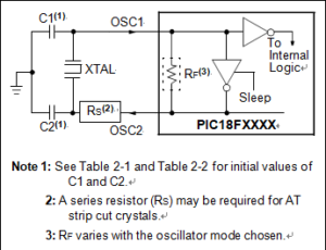
CRYSTAL used on Microcontroller PIC18F2439 Code Reverse Engineering
The oscillator design requires the use of a parallel cut crystal. Different capacitor values may be required to produce acceptable oscillator operation after Reverse Engineering W78E52B Chip Data. The user should test the performance of the oscillator over the expected VDD and temperature range for the application.
Обратный инжиниринг кода микроконтроллера PIC18F2439 может помочь разработчику скопировать исходный код с оригинального заблокированного микроконтроллера Microchip PIC18F2439 в формате двоичного файла или шестнадцатеричных данных с помощью разблокированного защищенного бита предохранителя микропроцессора PIC18F2439 и считывания встроенной прошивки из программной флэш-памяти и программной памяти EEPROM;
When using resonators with frequencies above 3.6 MHz, the use of HS mode, rather than XT mode, is recommended for the purpose of Attack Winbond W78E051A Protected Eeprom. HS mode may be used at any VDD for which the controller is rated. If HS is selected, it is possible that the gain of the oscillator will overdrive the resonator in order to Break Nuvoton W78E054 MCU Flash Memory. Therefore, a series resistor should be placed between the OSC2 pin and the resonator. As a good starting point, the recommended value of RS is 330Ù.
مهندسی معکوس کد میکروکنترلر PIC18F2439 می تواند به طراح کمک کند تا کد منبع را از MCU PIC18F2439 قفل شده با ریزتراشه اصلی در قالب فایل باینری یا داده هگزیمال از طریق باز کردن قفل ریزپردازنده ایمن PIC18F2439 و بازخوانی سیستم عامل تعبیه شده از حافظه نرم افزار فلش و e.p.
Recover PIC18F2431 MCU Locked Program
Recover PIC18F2431 MCU locked program needs to unlock encrypted microcontroller PIC18F2431 tamper resistance system, and extract embedded firmware also known as source code from secured microprocessor PIC18F2431 flash binary file memory or eeprom heximal data memory;
recover PIC18F2431 MCU locked program needs to unlock encrypted microcontroller PIC18F2431 tamper resistance system, and extract embedded firmware also known as source code from secured microprocessor PIC18F2431 flash binary file memory or eeprom heximal data memory
Besides its availability as a clock source when Microchip PIC18F2520 Embedded Firmware Extraction, the internal oscillator block provides a stable reference source that gives the family additional features for robust operation and hacker can technically Recover PIC18F2431 MCU Locked Program through power glitch on it:
- Fail-Safe Clock Monitor: This option constantly monitors the main clock source against a reference signal provided by the internal oscillator. If a clock failure occurs, the controller is switched to the internal oscillator block after Microchip MCU PIC16F870 Heximal Code Restoration, allowing for continued operation or a safe application shutdown.
Two-Speed Start-up: This option allows the internal oscillator to serve as the clock source from Power-on Reset, or wake-up from Sleep mode, until the primary clock source is available.
بازیابی PIC18F2431 برنامه قفل شده MCU باید سیستم مقاومت در برابر دستکاری میکروکنترلر رمزگذاری شده PIC18F2431 را باز کند و سیستم عامل تعبیه شده را که به عنوان کد منبع شناخته می شود از حافظه فایل باینری فلش ریزپردازنده ایمن PIC18F2431 یا حافظه داده هگزیمال eeprom استخراج کند.
- 12-Bit A/D Converter: This module incorporates programmable acquisition time, allowing for a channel to be selected and a conversion to be initiated without waiting for a sampling period and thus, reducing code overhead.
- Memory Endurance: The Enhanced Flash cells for both program memory and data EEPROM are rated to last for many thousands of erase/write cycles – up to 100,000 for program memory and 1,000,000 for EEPROM by Recover Freescale MCU MC9S12XDG128 Memory Program. Data retention without refresh is conservatively estimated to be greater than 40 years.
- Self-Programmability: These devices can write to their own program memory spaces under inter- nal software control. By using a bootloader routine located in the protected Boot Block at the top of program memory, it becomes possible to create an application that can update itself in the field.
- Extended Instruction Set: Recover PIC18F2431 MCU Locked Program introduces an optional extension to the PIC18 instruction set, which adds eight new instructions and an Indexed Addressing mode. This extension, enabled as a device con- figuration option, has been specifically designed to optimize re-entrant application code originally developed in high-level languages, such as C.
PIC18F2431 MCU लॉक किए गए प्रोग्राम को पुनर्प्राप्त करने के लिए एन्क्रिप्टेड माइक्रोकंट्रोलर PIC18F2431 छेड़छाड़ प्रतिरोध प्रणाली को अनलॉक करने की आवश्यकता है, और सुरक्षित माइक्रोप्रोसेसर PIC18F2431 फ्लैश बाइनरी फ़ाइल मेमोरी या ईप्रोम हेक्सिमल डेटा मेमोरी से एम्बेडेड फर्मवेयर को निकालने की आवश्यकता है जिसे स्रोत कोड के रूप में भी जाना जाता है
- Enhanced CCP module: In PWM mode, this module provides 1, 2 or 4 modulated outputs for controlling half-bridge and full-bridge drivers. Other features include auto-shutdown, for disabling PWM outputs on interrupt or other select conditions and auto-restart after Reverse Engineering Microchip PIC16F1913 Memory, to reactivate outputs once the condition has cleared.
- Enhanced Addressable USART: This serial communication module is capable of standard.
Recover PIC18F2431 MCU Locked Program
RS-232 operation and provides support for the LIN bus protocol. Other enhancements include automatic baud rate detection and a 16-bit Baud Rate Generator for improved resolution. When the microcontroller is using the internal oscillator block to Clone IC Code, the EUSART provides stable operation for applications that talk to the outside world without using an external crystal (or its accompanying power requirement).
- Extended Watchdog Timer (WDT): This enhanced version incorporates a 16-bit prescaler, allowing an extended time-out range that is stable across operating voltage and temperature.

recuperar o programa bloqueado do MCU PIC18F2431 precisa desbloquear o sistema de resistência à violação do microcontrolador PIC18F2431 criptografado e extrair o firmware incorporado, também conhecido como código-fonte, da memória de arquivo binário flash do microprocessador PIC18F2431 protegido ou da memória de dados hexadecimal eeprom
Break PIC18F2423 Protected Memory
Break PIC18F2423 protected memory and recover embedded firmware in the format of binary file or heximal data from secured PIC18F2423 microcontroller by MCU cracking technique,
break PIC18F2423 protected memory and recover embedded firmware in the format of binary file or heximal data from secured PIC18F2423 microcontroller by MCU cracking technique,
In this blog, we explore advanced methods to Break PIC18F2423 microcontroller Protected Memory. We delve into reverse engineering techniques used to access the firmware, recover source code, and extract binary or hexadecimal data from locked microcontroller PIC18F2423. Whether you’re working to restore lost code or break into secured systems for legitimate research, this guide provides insights into the complexities of microprocessor PIC18F2423 security. Learn how to tackle firmware protection, analyze memory layouts, and apply reverse engineering principles to retrieve sensitive information embedded within the chip.
حافظه محافظت شده PIC18F2423 را بشکنید و سیستم عامل تعبیه شده را در قالب فایل باینری یا داده های هگزیمال از میکروکنترلر ایمن PIC18F2423 با تکنیک کرک MCU بازیابی کنید.
NANO Watt technology has been applied on PIC18F2423 Microcontroller which bring much more difficulties in the process of Break PIC18F2423 Protected Memory:
All of the devices in the PIC18F2423 family incorporate a range of features that can significantly reduce power consumption during operation. Key items include:
• Alternate Run Modes: By clocking the controller from the Timer1 source or the internal oscillator block, power consumption during code execution can be reduced by as much as 90% after Recover PIC MCU Microchip 16LF506 Firmware.
• Multiple Idle Modes: The controller can also run with its CPU core disabled but the peripherals still active after Clone IC firmware. In these states, power consumption can be reduced even further, to as little as 4% of normal operation requirements.
• On-the-Fly Mode Switching: The power-managed modes are invoked by user code during operation, allowing the user to incorporate power-saving ideas into their application’s software design before Recover PIC MCU Microchip 12F510 Firmware.
• Low Consumption in Key Modules: The power requirements for both Timer1 and the Watchdog Timer are minimized.
Break PIC18F2423 Protected Memory
All of the devices in the PIC18LF2423 family offer ten different oscillator options, allowing users a wide range of choices in developing application hardware. These include:
• Four Crystal modes, using crystals or ceramic resonators.
• Two External Clock modes, offering the option of using two pins (oscillator input and a divide-by-4 clock output) or one pin (oscillator input, with the second pin reassigned as general I/O).
• Two External RC Oscillator modes with the same pin options as the External Clock modes.
• An internal oscillator block which provides an 8 MHz clock and an INTRC source (approximately 31 kHz) for the purpose of Copy Encrypted Microchip PIC18F2330 Heximal, as well as a range of six user-selectable clock frequencies, between 125 kHz to 4 MHz, for a total of 8 clock frequencies. This option frees the two oscillator pins for use as additional general purpose I/O.
MCU क्रैकिंग तकनीक द्वारा सुरक्षित PIC18F2423 माइक्रोकंट्रोलर से बाइनरी फ़ाइल या हेक्सिमल डेटा के प्रारूप में PIC18F2423 संरक्षित मेमोरी को तोड़ना और एम्बेडेड फर्मवेयर को पुनर्प्राप्त करना,
• A Phase Lock Loop (PLL) frequency multiplier, available to both the High-Speed Crystal and Internal Oscillator modes, which allows clock speeds of up to 40 MHz from the HS clock source. Used with the internal oscillator, the PLL gives users a complete selection of clock speeds when Decrypt Microchip PIC18F2321 MCU Heximal File, from 31 kHz to 32 MHz, all without using an external crystal or clock circuit.
quebrar a memória protegida do PIC18F2423 e recuperar o firmware incorporado no formato de arquivo binário ou dados hexagonais do microcontrolador PIC18F2423 protegido pela técnica de cracking do MCU,
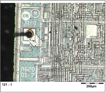
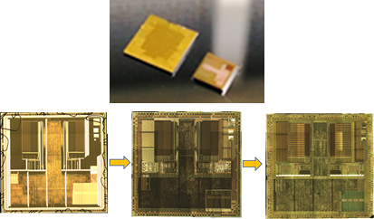
Restore Microprocessor Program Most Important Two Steps
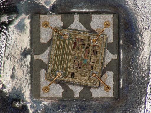
Restore microprocessor program need to use Focus Ion Beam to make the necessary modification on the microprocessor program after Break IC PIC16F88 Data, and hereby we would like to introduce these two steps separately, through inject the iodin steam can have a better corruption rate of restore microprocessor program.
Restoration can produce the metal layer windows on the bottom of microprocessor program for visiting without damage the coherent structure. Through the injection of organic gas with platinic can create the new connection on the microprocessor program restore. use other chemical component like insulators can download the ion beam into the bottom metal of microprocessor program and make connection with the surface metal when restore microprocessor program without get in touch with other cover layer.
Focus ion beam can move on the surface of microprocessor program with 0.1 micron preciseness regardless the microprocessor program surface structure and evenness. Use the infrared line for imaging and can locate the transistor on the microprocessor program from it back when Break IC PIC16F715 Firmware.
After we made some necessary electrical connection and cut out on the microprocessor program for restore purpose, we need to do it’s the modification on the microprocessor program circuit pattern when restore it. As we all know, it is not necessary to have the information from databus internally of microprocessor program restore by using the microprobe technology.
Sometimes, especially for the microprocessor program itself, cut off the metal interconnection wire or break the control circuit when Recover Microcontroller PIC16F506 Binary to seal off the security protection mechanism. Focus Ion Beam is very easy to re-connect the protection security states transmission wire to the ground or power supply layer when restore microprocessor program. Although microprobe can do the same work but it won’t work if the metal wire embedded very deeply.
Microcontroller Unlocking and modification at least need to find out the restore point through the reverse engineering process which means the job can’t be done by a restoreer with less experience and well equipped facilities.
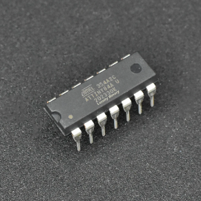
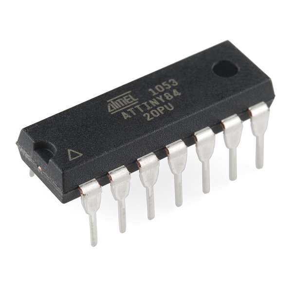
Break AVR MCU ATTINY84 Protected Source Code
In the world of electronics and embedded systems, reverse engineering plays a crucial role in understanding and replicating existing technologies. One of the common challenges faced by professionals and enthusiasts alike is to break AVR MCU ATTINY84 protected source code. This microcontroller, like many others in the AVR family, comes with security measures that prevent unauthorized access to its firmware. These protections are designed to safeguard intellectual property, making it difficult for others to copy or modify the original code. However, individuals with advanced skills in microcontroller and microprocessor systems often attempt to crack this security to access the embedded software.
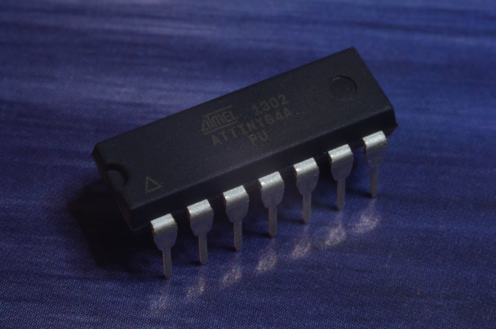
Reverse engineering of a microcontroller like the ATTINY84 typically involves using sophisticated hardware and software techniques to bypass these protections. These techniques might include analyzing the chip’s physical structure, probing its circuits, or exploiting potential vulnerabilities in the security features. While the practice of cracking protected source code can enable the duplication of proprietary firmware, it often raises ethical and legal concerns, especially when used for unauthorized copying or piracy.
прекъсване на AVR MCU ATtiny84 защитен изходен код от защитена флаш памет и криптирана eeprom памет, възстановяване на изгубен вграден фърмуер на оригиналния микроконтролер ATtiny84 чрез технология за обратно инженерство.
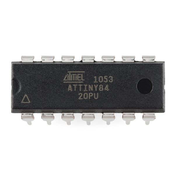
Break AVR MCU ATTINY84 protected source code and extract embedded firmware from secured microcontroller ATTINY84 by binary software or heximal program, copy ATTINY84 encrypted microprocessor content to new MCU;
Break AVR MCU ATTINY84 Protected Source Code
We can break AVR MCU ATTINY84 protected source code, please view the AVR MCU ATTINY84 features for your reference:
The MPLAB SIM Software Simulator allows code development in a PC-hosted environment by simulating the PIC MCUs and dsPIC® DSCs on an instruction level.
On any given instruction, the data areas can be examined or modified and stimuli can be applied from a comprehensive stimulus controller after Break Microcontroller ATMEGA324A Binary. Registers can be logged to files for further run-time analysis.
The trace buffer and logic analyzer display extend the power of the simulator to record and track program execution, actions on I/O, most peripherals and internal registers.
break AVR MCU ATTINY84 protected source code and extract embedded firmware from secured microcontroller ATTINY84 by binary software or heximal program, copy ATTINY84 encrypted microprocessor content to new MCU;
The MPLAB SIM Software Simulator fully supports symbolic debugging using the MPLAB C18 and MPLAB C30 C Compilers, and the MPASM and MPLAB ASM30 Assemblers to provide better support of Reverse engineering IC ATMEGA324PV Code.
The software simulator offers the flexibility to develop and debug code outside of the hardware laboratory environment, making it an excellent, economical software development tool.
The MPLAB ICE 2000 In-Circuit Emulator is intended to provide the product development engineer with a complete AVR MCU design tool set for PIC AVR MCUs. Software control of the MPLAB ICE 2000.
złamać chroniony kod źródłowy mikrokontrolera AVR ATTINY84 i wyodrębnić oprogramowanie sprzętowe z zabezpieczonego mikrokontrolera ATTINY84 za pomocą oprogramowania binarnego lub programu heksametalogowego, skopiować zaszyfrowaną zawartość mikroprocesora ATTINY84 do nowego mikrokontrolera;
In-Circuit Emulator is advanced by the MPLAB Integrated Development Environment, which allows editing, building, downloading and source debugging from a single environment.
The MPLAB ICE 2000 is a full-featured emulator system with enhanced trace to facilitate the progress of Reverse engineering Chip ATMEGA324 Code, trigger and data monitoring features. Interchangeable processor modules allow the system to be easily reconfigured for emulation of different processors.
взломать защищенный исходный код микроконтроллера AVR ATTINY84 и извлечь встроенную прошивку из защищенного микроконтроллера ATTINY84 с помощью двоичного программного обеспечения или шестнадцатеричной программы, скопировать зашифрованное содержимое микропроцессора ATTINY84 в новый микроконтроллер;
The architecture of the MPLAB ICE 2000 In-Circuit Emulator allows expansion to support Break Microcontroller ATMEGA164PV Code. The MPLAB ICE 2000 In-Circuit Emulator system has been designed as a real-time emulation system with advanced features that are typically found on more expensive development tools.
The PC platform and Microsoft® Windows® 32-bit operating system were chosen to best make these features available in a simple, unified application by Crack MCU Program.
बाइनरी सॉफ्टवेयर या हेक्सिमल प्रोग्राम द्वारा AVR MCU ATTINY84 संरक्षित स्रोत कोड को तोड़ना और सुरक्षित माइक्रोकंट्रोलर ATTINY84 से एम्बेडेड फर्मवेयर निकालना, ATTINY84 एन्क्रिप्टेड माइक्रोप्रोसेसर सामग्री को नए MCU में कॉपी करना;