Break PIC18F2450 Microcontroller Locked Heximal
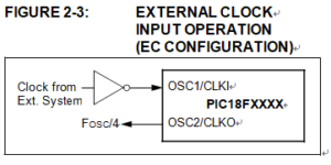
The EC and ECIO Oscillator modes require an external clock source to be connected to the OSC1 pin. There is no oscillator start-up time required after a Power-on Reset or after Break PIC18F2450 Microcontroller Locked Heximal. In the EC Oscillator mode, the oscillator frequency divided by 4 is available on the OSC2 pin. This signal may be used for test purposes or to synchronize other logic. Below Figure shows the pin connections for the EC Oscillator mode.
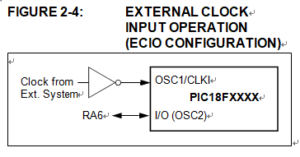
The ECIO Oscillator mode functions like the EC mode, except that the OSC2 pin becomes an additional general purpose I/O pin when Clone IC program. The I/O pin becomes bit 6 of PORTA (RA6). Figure 2-4 shows the pin connections for the ECIO Oscillator mode.
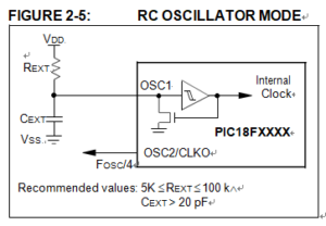
For timing insensitive applications, the “RC” and “RCIO” device options offer additional cost savings. The actual oscillator frequency is a function of several factors:
- supply voltage
- values of the external resistor (REXT) and capacitor (CEXT)
- operating temperature
Break PIC18F2450 Microcontroller Locked Heximal
Given the same device, operating voltage and temperature and component values, there will also be unit-to-unit frequency variations. These are due to factors such as:
- normal manufacturing variation
- difference in lead frame capacitance between package types (especially for low CEXT values)
- variations within the tolerance of limits of REXT and CEXT
In the RC Oscillator mode, the oscillator frequency divided by 4 is available on the OSC2 pin. This signal may be used for test purposes or to synchronize other logic. Figure 2-5 shows how the R/C combination is connected.