 Losted PIC18F2458 Microcontroller Embedded Code Restoration
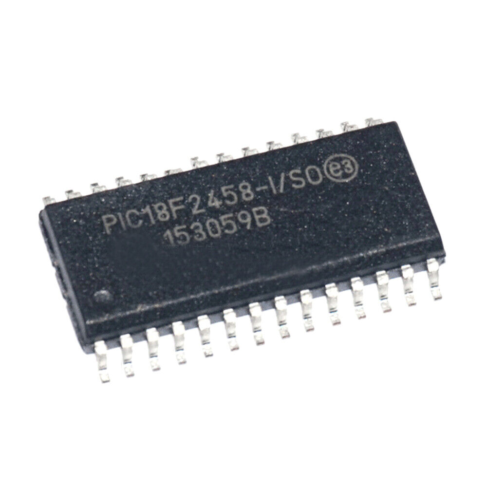
Losted PIC18F2458 microcontroller embedded code restoration is a process to recover binary file or heximal data from PIC18F2458 protective MICROCHIP MCU flash memory and eeprom memory, through PIC18F2458 microprocessor fuse bit unlocking technique;
losted PIC18F2458 microcontroller embedded code restoration is a process to recover binary file or heximal data from PIC18F2458 protective MICROCHIP MCU flash memory and eeprom memory, through PIC18F2458 microprocessor fuse bit unlock technique;
Without the back-up embedded firmware from microcontrollers sometimes could become the disaster for a company which try to rescue the obselete or not-produce-anymore devices, through our techniques, Losted PIC18F2458 Microcontroller Embedded Code Restoration process will help you get the firmware back from original PIC18F2458:
The HSPLL mode makes use of the HS mode oscillator for frequencies up to 10 MHz. A PLL then multiplies the oscillator output frequency by 4 to produce an internal clock frequency up to 40 MHz. The PLLEN bit is not available in this oscillator mode before Microchip PIC18F2520 Embedded Firmware Extraction.
Восстановление встроенного кода потерянного микроконтроллера PIC18F2458 представляет собой процесс восстановления двоичного файла или шестнадцатеричных данных из защитной флэш-памяти микроконтроллера MICROCHIP PIC18F2458 и памяти EEPROM с помощью техники разблокировки бита предохранителя микропроцессора PIC18F2458;
The PLL is only available to the crystal oscillator when the FOSC3:FOSC0 Configuration bits are programmed for HSPLL mode (= 0110).
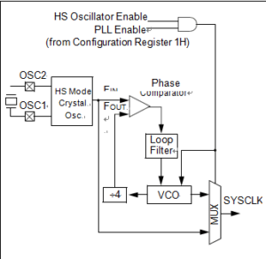
PLL BLOCK DIAGRAM
The PLL is also available to the internal oscillator block when the INTOSC is configured as the primary clock source from Microchip MCU PIC16F870 Heximal Code Restoration. In this configuration, the PLL is enabled in soft- ware and generates a clock output of up to 32 MHz.
The PIC18LF2458 devices include an internal oscillator block which generates two different clock signals; either can be used as the micro- controller’s clock source. This may eliminate the need for external oscillator circuits on the OSC1 and/or OSC2 pins in order to Recover Freescale MCU MC9S12XDG128 Memory Program.
kaybolan PIC18F2458 mikrodenetleyici gömülü kod restorasyonu, PIC18F2458 koruyucu MICROCHIP MCU flaş belleğinden ve eeprom belleğinden, PIC18F2458 mikroişlemci sigorta biti kilit açma tekniği aracılığıyla ikili dosya veya onaltılık verileri kurtarmak için bir işlemdir;
The main output (INTOSC) is an 8 MHz clock source, which can be used to directly drive the device clock. It also drives a postscaler, which can provide a range of clock frequencies from 31 kHz to 4 MHz. The INTOSC output is enabled when a clock frequency from 125 kHz to 8 MHz is selected, and can provide 31 kHz if required.
Losted PIC18F2458 Microcontroller Embedded Code Restoration
The other clock source is the internal RC oscillator (INTRC) which provides a nominal 31 kHz output after Reverse Engineering Microchip PIC16F1913 Memory. INTRC is enabled if it is selected as the device clock source; it is also enabled automatically when any of the following are enabled:
• Power-up Timer
• Fail-Safe Clock Monitor
• Watchdog Timer
These features are discussed in greater detail in Section 23.0 “Special Features of the CPU”.
The clock source frequency (INTOSC direct, INTRC direct or INTOSC postscaler) is selected by configuring the IRCF bits of the OSCCON register before Unlock Microcontroller Flash. Additionally, the 31 kHz clock can be provided by either the INTOSC, or INTRC clock sources, depending on the INTSRC bit (OSCTUNE<7>).
استعادة الكود المضمن في متحكم PIC18F2458 المفقود هي عملية لاستعادة ملف ثنائي أو بيانات سداسية من ذاكرة فلاش MCU الواقية PIC18F2458 وذاكرة EEPROM، من خلال تقنية فتح بت الصمامات للمعالج الدقيق PIC18F2458؛