 Copy PIC18F2480 MCU Locked Heximal
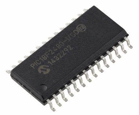
Copy PIC18F2480 Microchip MCU locked heximal out from secured microcontroller PIC18F2480 flash program memory and eeprom data memory needs to unlock protective PIC18F2480 microprocessor’s fuse bit, read embedded firmware out of binary file or heximal source code;
copy PIC18F2480 Microchip MCU locked heximal out from secured microcontroller PIC18F2480 flash program memory and eeprom data memory needs to unlock protective PIC18F2480 microprocessor’s fuse bit, read embedded firmware out of binary file or heximal source code;
Using the internal oscillator as the clock source eliminates the need for up to two external oscillator pins when Crack MCU Firmware, which can then be used for digital I/O and Copy PIC18F2480 MCU Locked Heximal. Two distinct configurations are available:
- In INTIO1 mode, the OSC2 pin outputs FOSC/4, while OSC1 functions as RA7 for digital input and output.
- In INTIO2 mode, OSC1 functions as RA7 and OSC2 functions as RA6, both for digital input and output.

copiar PIC18F2480 Microchip MCU bloqueado heximal de la memoria de programa flash PIC18F2480 del microcontrolador protegido y la memoria de datos EEPROM necesita desbloquear el bit fusible del microprocesador PIC18F2480 protector, leer el firmware incorporado del archivo binario o código fuente heximal;
The internal oscillator block is calibrated at the factory to produce an INTOSC output frequency of 8.0 MHz when Recover Atmel AVR Controller ATmega48V Firmware.
The INTRC oscillator operates independently of the INTOSC source. Any changes in INTOSC across voltage and temperature are not necessarily reflected by changes in INTRC and vice versa.
Copy PIC18F2480 MCU Locked Heximal
The internal oscillator’s output has been calibrated at the factory but can be adjusted in the user’s applica- tion. This is done by writing to the OSCTUNE register from Break Atmel AVR MCU ATmega8535L Heximal.
When the OSCTUNE register is modified, the INTOSC frequency will begin shifting to the new frequency. The INTOSC clock will stabilize within 1 ms. Code execu- tion continues during this shift after Break IC ATmega88V Internal Flash. There is no indication that the shift has occurred.
скопируйте заблокированный шестнадцатеричный код микроконтроллера PIC18F2480 из защищенного микроконтроллера. Необходимо разблокировать защитный бит предохранителя микропроцессора PIC18F2480 во флэш-памяти программ и памяти данных EEPROM, считать встроенную прошивку из двоичного файла или шестнадцатеричного исходного кода;
The OSCTUNE register also implements the INTSRC and PLLEN bits, which control certain features of the internal oscillator block. The INTSRC bit allows users to select which internal oscillator provides the clock source when the 31 kHz frequency option is selected when Restore Microprocessor Program Most Important Two Steps. This is covered in greater detail in Section 2.7.1 “Oscillator Control Register”. The PLLEN bit controls the operation of the frequency multiplier, PLL, in Internal Oscillator modes.
PIC18F2480 마이크로칩 MCU를 보안 마이크로컨트롤러 PIC18F2480 플래시 프로그램 메모리와 EEPROM 데이터 메모리에서 잠긴 16진수를 복사하여 보호 PIC18F2480 마이크로프로세서의 퓨즈 비트를 잠금 해제하고, 이진 파일이나 16진수 소스 코드에서 임베디드 펌웨어를 읽어야 합니다.