 Reverse PIC18F2685 MCU Eprom Code
 August 27th, 2018 |
 Author:
Reverse engineering encrypted PIC18F2685 MCU eprom code is a process starts from unlock secured PIC18F2685 microcontroller protective system, retrieve protective embedded firmware content from PIC18F2685 microprocessor flash program memory and eeprom data memory in the format of binary code or heximal software;

Reverse engineering encrypted PIC18F2685 MCU eprom code is a process starts from unlock secured PIC18F2685 microcontroller protective system, retrieve protective embedded firmware content from PIC18F2685 microprocessor flash program memory and eeprom data memory in the format of binary code or heximal software
An exit from Sleep mode or any of the Idle modes is triggered by an interrupt from Crack MCU Program, a Reset or a WDT time-out. This section discusses the triggers that cause exits from power-managed modes from Reverse PIC18F2685 MCU Eprom Code. The clocking subsystem actions are discussed in each of the power-managed modes.
Any of the available interrupt sources can cause the device to exit from an Idle mode or the Sleep mode to a Run mode. To enable this functionality, an interrupt source must be enabled by setting its enable bit in one of the INTCON or PIE registers when Reverse Engineering MCU ATMEGA324PV heximal, The exit sequence is initiated when the corresponding interrupt flag bit is set.

L’ingénierie inverse du code EEPROM crypté du microcontrôleur PIC18F2685 est un processus qui commence par le déverrouillage du système de protection sécurisé du microcontrôleur PIC18F2685, la récupération du contenu du micrologiciel intégré de protection à partir de la mémoire de programme flash du microprocesseur PIC18F2685 et de la mémoire de données EEPROM au format de code binaire ou de logiciel hexadécimal ;
On all exits from Idle or Sleep modes by interrupt, code execution branches to the interrupt vector if the GIE/ GIEH bit (INTCON<7>) is set. Otherwise, code execution continues or resumes without branching.
Reverse PIC18F2685 MCU Eprom Code
A fixed delay of interval TCSD following the wake event is required when leaving Sleep and Idle modes. This delay is required for the CPU to prepare for execution after Recover MCU ATMEGA324A firmware. Instruction execution resumes on the first clock cycle following this delay.
A WDT time-out will cause different actions depending on which power-managed mode the device is in when the time-out occurs. If the device is not executing code (all Idle modes and Sleep mode), the time-out will result in an exit from the power-managed mode for the purpose of Break Microcontroller ATmega324PA binary, If the device is executing code from Reverse PIC18F2685 MCU Eprom Code (all Run modes), the time-out will result in a WDT Reset.
reverse engineering van gecodeerde PIC18F2685 MCU eprom-code is een proces dat begint met het ontgrendelen van het beveiligde PIC18F2685 microcontrollerbeveiligingssysteem, het ophalen van beschermende ingebedde firmware-inhoud uit het flashprogrammageheugen en eeprom-datageheugen van de PIC18F2685 microprocessor in de vorm van binaire code of heximale software;
The WDT timer and postscaler are cleared by executing a SLEEP or CLRWDT instruction, the loss of a currently selected clock source (if the Fail-Safe Clock Monitor is enabled) and modifying the IRCF bits in the OSCCON register from Break IC ATMEGA644 eeprom if the internal oscillator block is the device clock source.

सुरक्षित PIC18F4220 माइक्रोप्रोसेसर से बाइनरी प्रोग्राम या हेक्सिमल डेटा के एम्बेडेड फर्मवेयर को पुनर्स्थापित करने के लिए PIC18F4220 माइक्रोकंट्रोलर फ्लैश मेमोरी और ईप्रोम मेमोरी फ्यूज बिट को तोड़ें, मूल सुरक्षात्मक माइक्रोचिप MCU PIC18F4220 डिक्रिप्शन एक विनाशकारी प्रक्रिया है;
 Posted in

Recover PIC18F2682 Microcontroller Flash Program
Recover PIC18F2682 Microcontroller Flash Program and eeprom data program needs to decrypt protective MICROCHIP PIC18F2682 microprocessor tamper resistance system, copy original secured MCU PIC18F2682 embedded firmware to new chip;
recover PIC18F2682 microcontroller flash program and eeprom data program needs to decrypt protective MICROCHIP PIC18F2682 microprocessor tamper resistance system, copy original secured MCU PIC18F2682 embedded firmware to new chip;
In RC_IDLE mode, the CPU is disabled but the peripherals continue to be clocked from the internal oscillator block using the INTOSC multiplexer which is also critical for Recover PIC18F2682 Microcontroller Flash Program. This mode allows for controllable power conservation during Idle periods. From RC_RUN, this mode is entered by setting the IDLEN bit and executing a SLEEP instruction when Crack MCU Eeprom.
PIC18F2682 mikrodenetleyici flaş programını ve eeprom veri programını kurtarmak için koruyucu MICROCHIP PIC18F2682 mikroişlemci kurcalama direnci sistemini şifresini çözmek, orijinal güvenli MCU PIC18F2682 gömülü aygıt yazılımını yeni çipe kopyalamak gerekir;
If the device is in another Run mode, first set IDLEN, then set the SCS1 bit and execute SLEEP of Break chip ATMEGA861P code. Although its value is ignored, it is recommended that SCS0 also be cleared; this is to maintain software compatibility with future devices. The INTOSC multiplexer may be used to select a higher clock frequency by modifying the IRCF bits before executing the SLEEP instruction.
odzyskanie programu flash mikrokontrolera PIC18F2682 i danych eeprom; program wymaga odszyfrowania ochronnego systemu zabezpieczającego przed manipulacją mikroprocesora MICROCHIP PIC18F2682, skopiowanie oryginalnego zabezpieczonego oprogramowania wbudowanego MCU PIC18F2682 na nowy układ;
When the clock source is switched to the INTOSC multiplexer, the primary oscillator is shut down and the OSTS bit is cleared. If the IRCF bits are set to any non-zero value, or the INTSRC bit is set, the INTOSC output is enabled. The IOFS bit becomes set of Recover Microprocessor ATmega640V firmware, after the INTOSC output becomes stable, after an interval of TIOBST.
Recover PIC18F2682 Microcontroller Flash Program
Clocks to the peripherals continue while the INTOSC source stabilizes. If the IRCF bits were previously at a non-zero value to Reverse Engineering MCU ATtiny48V eeprom or INTSRC was set before the SLEEP instruction was executed and the INTOSC source was already stable, the IOFS bit will remain set by Recover PIC18F2682 Microcontroller Flash Program. If the IRCF bits and INTSRC are all clear, the INTOSC output will not be enabled, the
IOFS bit will remain clear and there will be no indication of the current clock source. When a wake event occurs, the peripherals continue to be clocked from the INTOSC multiplexer. After a delay of TCSD following the wake event, the CPU begins executing code being clocked by the INTOSC multiplexer to support the process of Recover Microcontroller ATmega324V data, The IDLEN and SCS bits are not affected by the wakeup. The INTRC source will continue to run if either the WDT or the Fail-Safe Clock Monitor is enabled.

восстановление программы флэш-памяти микроконтроллера PIC18F2682 и данных EEPROM программы, необходимой для расшифровки защитной системы защиты микропроцессора MICROCHIP PIC18F2682 от несанкционированного доступа, копирование оригинальной защищенной встроенной прошивки MCU PIC18F2682 на новый чип;
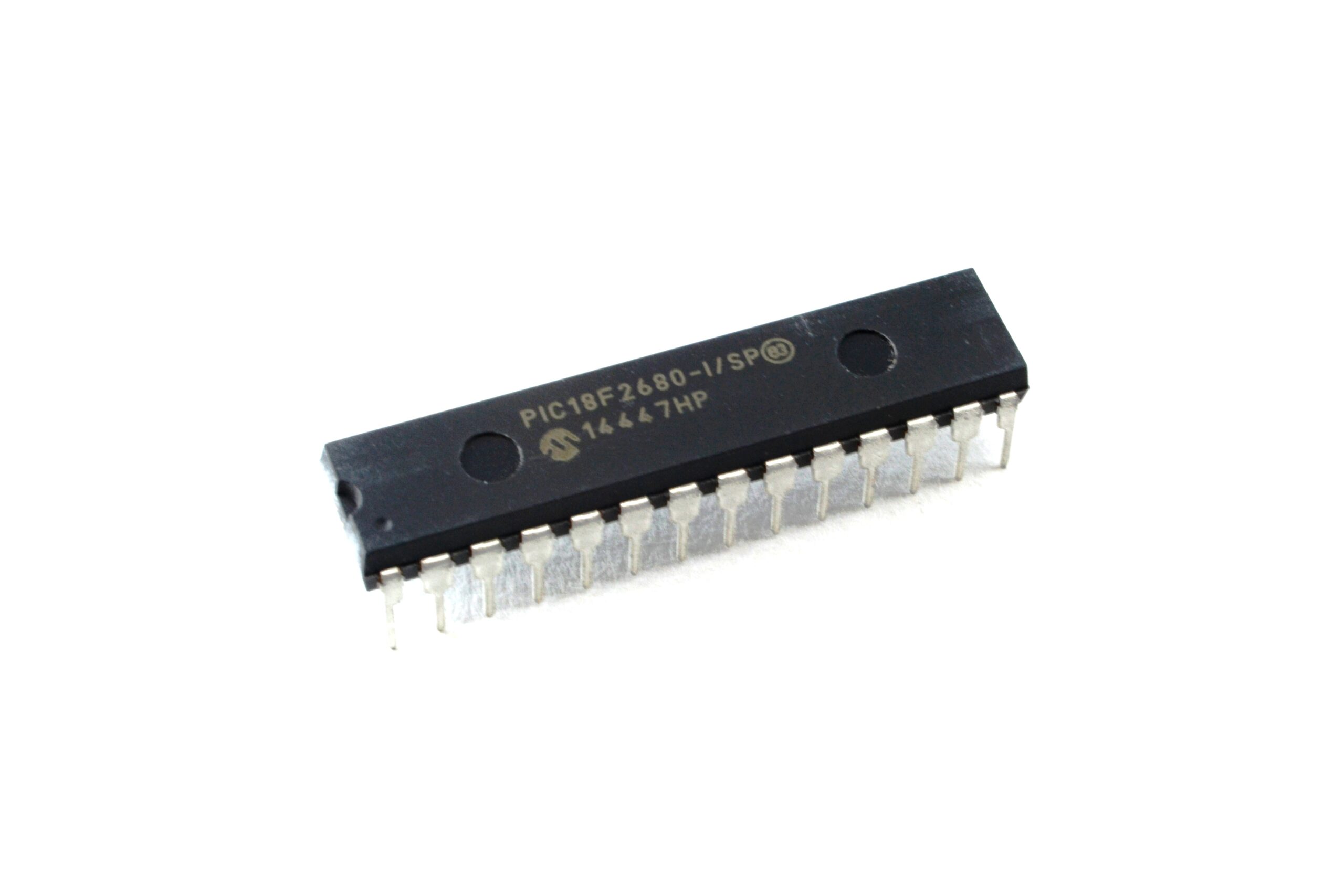
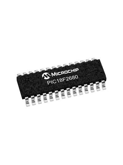
Break PIC18F2680 MCU Eeprom Memory
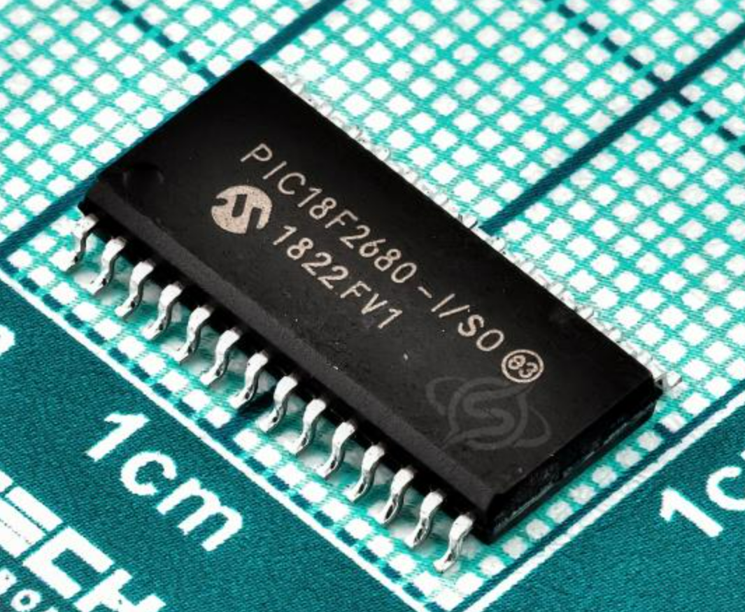
Break PIC18F2680 MCU eeprom memory content can help engineer restore embedded readout-protective firmware from locked PIC18F2680 microcontroller and copy encrypted PIC18F2680 MICROCHIP microprocessor flash program memory binary file or heximal code;
break PIC18F2680 MCU eeprom memory content can help engineer restore embedded readout-protective firmware from locked PIC18F2680 microcontroller and copy encrypted PIC18F2680 MICROCHIP microprocessor flash program memory binary file or heximal code;
This mode is unique among the three low-power Idle modes, in that it does not disable the primary device clock when Break PIC18F2680 MCU Eeprom Memory. For timing sensitive applications, this allows for the fastest resumption of device operation with its more accurate primary clock source, since the clock source does not have to “warm-up” or transition from another oscillator when Recover Locked Chip ATMEGA128PV Binary.
Break PIC18F2680 MCU Eeprom Memory
PRI_IDLE mode is entered from PRI_RUN mode by setting the IDLEN bit and executing a SLEEP instruction when Crack MCU Firmware. If the device is in another Run mode, set IDLEN first, then clear the SCS bits and execute SLEEP to Decrypt Locked MCU ATMEGA128V Embedded Firmware. Although the CPU is disabled, the peripherals continue to be clocked from the primary clock source specified by the FOSC3:FOSC0 Configuration bits. The OSTS bit remains set (see below Figure).
Взлом содержимого памяти EEPROM микроконтроллера PIC18F2680 может помочь инженеру восстановить встроенную защитную прошивку из заблокированного микроконтроллера PIC18F2680 и скопировать зашифрованный двоичный файл или шестнадцатеричный код флэш-памяти микропроцессора PIC18F2680 MICROCHIP;
When a wake event occurs, the CPU is clocked from the primary clock source. A delay of interval TCSD is required between the wake event and when code execution starts. This is required to allow the CPU to become ready to execute instructions. After the wake- up, the OSTS bit remains set. The IDLEN and SCS bits are not affected by the wake-up for the purpose of Dump Microcontroller ATMEGA128V Locked Code (see below Figure).
Złamanie zawartości pamięci EEPROM mikrokontrolera PIC18F2680 może pomóc inżynierowi przywrócić wbudowane oprogramowanie zabezpieczające przed odczytem z zablokowanego mikrokontrolera PIC18F2680 i skopiować zaszyfrowany plik binarny lub kod heksadecymalny pamięci programu mikroprocesora PIC18F2680 MICROCHIP;
The Timer1 oscillator should already be running prior to entering SEC_IDLE mode. If the T1OSCEN bit is not set when the SLEEP instruction is executed, the SLEEP instruction will be ignored and entry to SEC_IDLE mode will not occur through Decrypt Microprocessor ATMEGA169PA Code. If the Timer1 oscillator is enabled but not yet running, peripheral clocks will be delayed until the oscillator has started. In such sit- uations, initial oscillator operation is far from stable and unpredictable operation may result.
PIC18F2680 MCU eeprom bellek içeriğini kırmak, mühendisin kilitli PIC18F2680 mikrodenetleyicisinden gömülü okuma korumalı aygıt yazılımını geri yüklemesine ve şifrelenmiş PIC18F2680 MICROCHIP mikroişlemci flaş program belleği ikili dosyasını veya onaltılık kodunu kopyalamasına yardımcı olabilir;
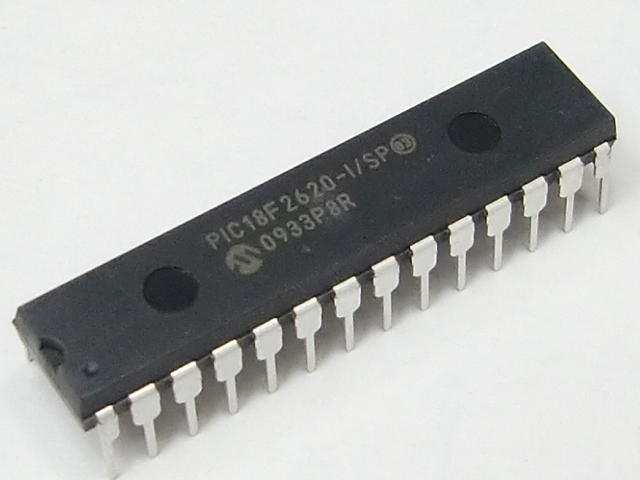
Recover PIC18F2620 Microprocessor Eeprom Program
Microcontroller PIC16LF716 embedded firmware decryption is a process to unlock encrypted MICROCHIP MCU PIC16LF716 flash program memory and eeprom data memory, and retrieve embedded firmware from secured PIC16LF716 microprocessor by the binary file or heximal code;
microcontroller PIC16LF716 embedded firmware decryption is a process to unlock encrypted MICROCHIP MCU PIC16LF716 flash program memory and eeprom data memory, and retrieve embedded firmware from secured PIC16LF716 microprocessor by the binary file or heximal code;
The Idle modes allow the controller’s CPU to be Recover PIC18F2620 Microprocessor Eeprom Program while the peripherals continue to operate. Selecting a particular Idle mode allows users to further manage power consumption.
If the IDLEN bit is set to a ‘1’ when a SLEEP instruction is executed, the peripherals will be clocked from the clock source selected using the SCS1:SCS0 bits; however, the CPU will not be clocked. The clock source status bits are not affected when Break IC ATmega640A Secured Flash. Setting IDLEN and executing a SLEEP instruction provides a quick method of switching from a given Run mode to its corresponding Idle mode.
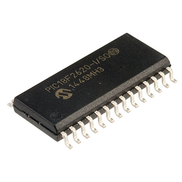
A descriptografia do firmware incorporado do microcontrolador PIC16LF716 é um processo para desbloquear a memória de programa flash criptografada do MICROCHIP MCU PIC16LF716 e a memória de dados eeprom, e recuperar o firmware incorporado do microprocessador PIC16LF716 protegido pelo arquivo binário ou código hexadecimal;
If the WDT is selected, the INTRC source will continue to operate. If the Timer1 oscillator is enabled, it will also continue to run. Since the CPU is not executing instructions, the only exits from any of the Idle modes are by interrupt, WDT time-out or a Reset to prevent the process of Decrypt Secured MCU ATMEGA128P Code.
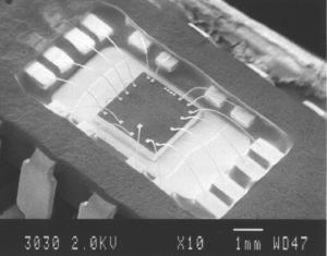
Recover PIC18F2620 Microprocessor Eeprom Program
When a wake event occurs, CPU execution is delayed by an interval of TCSD (parameter 38, Table 26-10) while it becomes ready to execute code when Crack MCU Flash. When the CPU begins executing code from Recover PIC18F2620 Microprocessor Eeprom Program, it resumes with the same clock source for the current Idle mode.
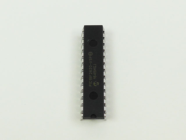
माइक्रोकंट्रोलर PIC16LF716 एम्बेडेड फर्मवेयर डिक्रिप्शन एन्क्रिप्टेड माइक्रोचिप MCU PIC16LF716 फ्लैश प्रोग्राम मेमोरी और ईप्रोम डेटा मेमोरी को अनलॉक करने और बाइनरी फ़ाइल या हेक्सिमल कोड द्वारा सुरक्षित PIC16LF716 माइक्रोप्रोसेसर से एम्बेडेड फर्मवेयर को पुनः प्राप्त करने की एक प्रक्रिया है;
For example, when waking from RC_IDLE mode, the internal oscillator block will clock the CPU and peripherals (in other words, RC_RUN mode). The IDLEN and SCS bits are not affected by the wake-up for the purpose of Reverse Engineering IC ATMEGA88PV Locked Flash. While in any Idle mode or the Sleep mode, a WDT time-out will result in a WDT wake-up to the Run mode currently specified by the SCS1:SCS0 bits.
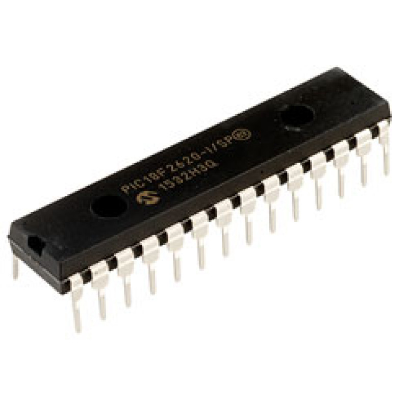
Декриптирането на вграден фърмуер на микроконтролер PIC16LF716 е процес за отключване на криптирана флаш програмна памет на MICROCHIP MCU PIC16LF716 и памет за данни на eeprom и извличане на вграден фърмуер от защитен микропроцесор PIC16LF716 чрез двоичен файл или шестнадесетичен код;
Break PIC18F2610 MCU Flash Memory
Break PIC18F2610 MCU flash memory protection and readout embedded firmware in the format of binary data or heximal source code from protective microcontroller PIC18F2610, copy flash memory program or eeprom memory content to new encrypted PIC18F2610 microprocessor;
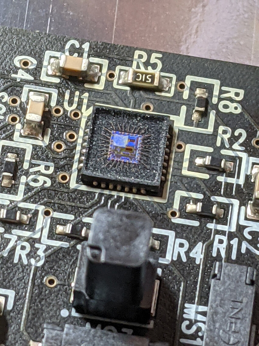
break PIC18F2610 MCU flash memory protection and readout embedded firmware in the format of binary data or heximal source code from protective microcontroller PIC18F2610, copy flash memory program or eeprom memory content to new encrypted PIC18F2610 microprocessor;
The power-managed Sleep mode in the PIC18F2610 devices is identical to the legacy Sleep mode offered in all other PIC devices. It is entered by clearing the IDLEN bit (the default state on device Reset) and executing the SLEEP instruction which faciliate the process of Break PIC18F2610 MCU Flash Memory.
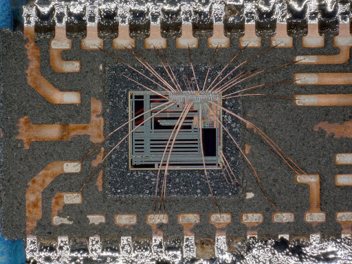
quebrar a proteção de memória flash do MCU PIC18F2610 e ler o firmware incorporado no formato de dados binários ou código-fonte hexadecimal do microcontrolador de proteção PIC18F2610, copiar o programa de memória flash ou o conteúdo da memória eeprom para o novo microprocessador PIC18F2610 criptografado;
This shuts down the selected oscillator (below Figure) after Break IC PIC12F615 Software. All clock source status bits are cleared. Entering the Sleep mode from any other mode does not require a clock switch to Break IC PIC12F635 Program. This is because no clocks are needed once the controller has entered Sleep. If the WDT is selected, the INTRC source will continue to operate. If the Timer1 oscillator is enabled for the purpose of Break IC PIC16F616 Heximal, it will also continue to run.
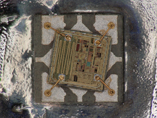
прекъсване на защитата на флаш паметта на PIC18F2610 MCU и вграден фърмуер за четене във формат на двоични данни или шестнадесетичен изходен код от защитен микроконтролер PIC18F2610, копиране на програма за флаш памет или съдържание на eeprom памет към нов криптиран микропроцесор PIC18F2610;
When a wake event occurs in Sleep mode (by interrupt, Reset or WDT time-out), the device will not be clocked until the clock source selected by the SCS1:SCS0 bits becomes ready (see Figure 3-6), or it will be clocked from the internal oscillator block when Break IC PIC12F609 Heximal if either the Two-Speed Start-up or the Fail-Safe Clock Monitor are enabled (see Section 23.0 “Special Features of the CPU”).
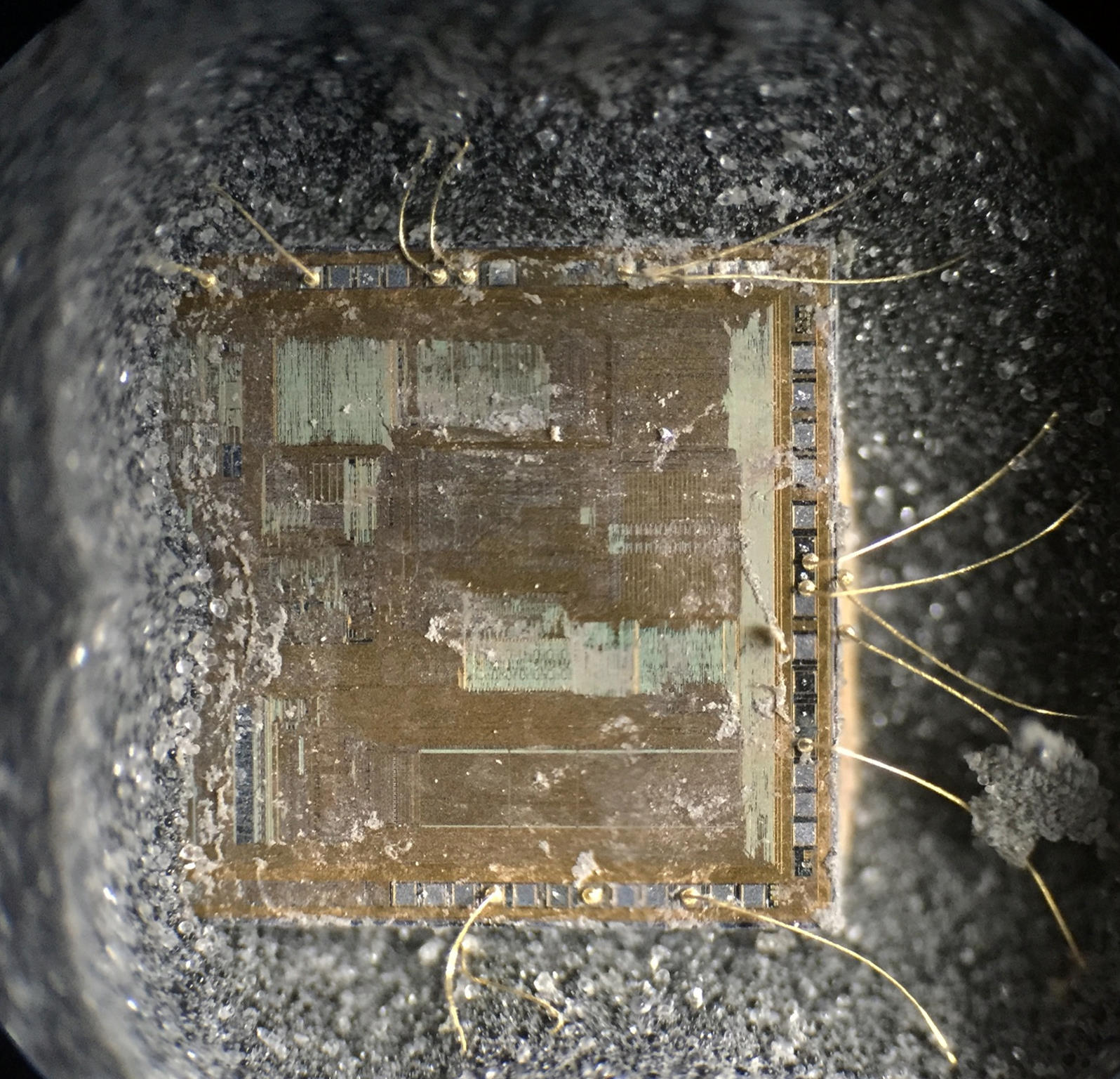
PIC18F2610 MCU फ्लैश मेमोरी सुरक्षा को तोड़ना और सुरक्षात्मक माइक्रोकंट्रोलर PIC18F2610 से बाइनरी डेटा या हेक्सिमल स्रोत कोड के प्रारूप में एम्बेडेड फर्मवेयर को पढ़ना, फ्लैश मेमोरी प्रोग्राम या ईप्रोम मेमोरी सामग्री को नए एन्क्रिप्टेड PIC18F2610 माइक्रोप्रोसेसर में कॉपी करना;
In either case, the OSTS bit is set when the primary clock is providing the device clocks. The IDLEN and SCS bits are not affected by the wake-up from Crack MCU Software.
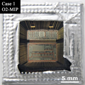
Break PIC18F2610 MCU Flash Memory
Reverse Engineering PIC18F2580 Processor Embedded Software
Reverse engineering PIC18F2580 processor embedded software starts from unlock secured microcontroller PIC18F2580 tamper resistance, copy embedded firmware of binary file or heximal data from MICROCHIP PIC18F2580 encrypted MCU flash program memory and eeprom data memory;

reverse engineering PIC18F2580 processor embedded software starts from unlock secured microcontroller PIC18F2580 tamper resistance, copy embedded firmware of binary file or heximal data from MICROCHIP PIC18F2580 encrypted MCU flash program memory and eeprom data memory;
This mode is entered by setting the SCS1 bit to ‘1’. Although it is ignored, it is recommended that the SCS0 bit also be cleared; this is to maintain software compatibility with future devices. When the clock source is switched to the INTOSC multiplexer when Break IC ATmega324V Protected Firmware (see below Figure), the primary oscillator is shut down and the OSTS bit is cleared by Reverse Engineering PIC18F2580 Processor Embedded Software. The IRCF bits may be modified at any time to immediately change the clock speed.
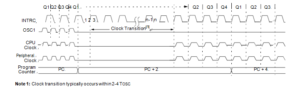
Caution should be used when modifying a single IRCF bit. If VDD is less than 3V, it is possible to select a higher clock speed than is supported by the low VDD. Improper device operation may result if the VDD/FOSC specifications are violated for the purpose of Decode Locked Microprocessor ATmega324A Source Code.
If the IRCF bits and the INTSRC bit are all clear, the INTOSC output is not enabled and the IOFS bit will remain clear; there will be no indication of the current clock source. The INTRC source is providing the device clocks.
If the IRCF bits are changed from all clear (thus, enabling the INTOSC output) or if INTSRC is set by Crack MCU Eeprom, the IOFS bit becomes set after the INTOSC output becomes stable. Clocks to the device continue while the INTOSC source stabilizes after an interval of TIOBST.
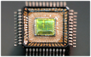
Reverse Engineering PIC18F2580 Processor Embedded Software
If the IRCF bits were previously at a non-zero value, or if INTSRC was set before setting SCS1 and the INTOSC source was already stable, the IOFS bit will remain set by Dump Microcontroller ATMEGA1284V Source Code.

วิศวกรรมย้อนกลับซอฟต์แวร์ฝังตัวของโปรเซสเซอร์ PIC18F2580 เริ่มจากปลดล็อคไมโครคอนโทรลเลอร์ PIC18F2580 ที่ได้รับการรักษาความปลอดภัย ป้องกันการดัดแปลง คัดลอกเฟิร์มแวร์ที่ฝังไว้ของไฟล์ไบนารีหรือข้อมูลเลขฐานสิบหกจากหน่วยความจำโปรแกรมแฟลช MCU ที่เข้ารหัส PIC18F2580 และหน่วยความจำข้อมูล EEPROM
On transitions from RC_RUN mode to PRI_RUN mode, the device continues to be clocked from the INTOSC multiplexer while the primary clock is started. When the primary clock becomes ready for Reverse Engineering PIC18F2580 Processor Embedded Software, a clock switch to the pri- mary clock occurs (see below Figure).

Kỹ thuật đảo ngược phần mềm nhúng của bộ vi điều khiển PIC18F2580 bắt đầu từ việc mở khóa khả năng chống giả mạo của vi điều khiển PIC18F2580 được bảo mật, sao chép chương trình cơ sở nhúng của tệp nhị phân hoặc dữ liệu thập lục phân từ bộ nhớ chương trình flash MCU được mã hóa MICROCHIP PIC18F2580 và bộ nhớ dữ liệu eeprom;
When the clock switch is complete, the IOFS bit is cleared, the OSTS bit is set and the primary clock is providing the device clock. The IDLEN and SCS bits are not affected by the switch from Reverse Engineering Chip ATmega640PV Locked Flash. The INTRC source will continue to run if either the WDT or the Fail-Safe Clock Monitor is enabled.

Обратное проектирование встроенного программного обеспечения процессора PIC18F2580 начинается с разблокировки защищенного микроконтроллера PIC18F2580, защиты от несанкционированного доступа, копирования встроенной прошивки двоичного файла или шестнадцатеричных данных из зашифрованной флэш-памяти программ микроконтроллера MICROCHIP PIC18F2580 и памяти данных EEPROM;
Microchip PIC18F2553 MCU Heximal Recovering
Microchip PIC18F2553 MCU heximal recovering can help engineer to restore embedded source code from secured microcontroller PIC18F2553 flash program memory and eeprom data memory, then engineer will be able to copy firmware binary file or heximal data to new microprocessor PIC18F2553;
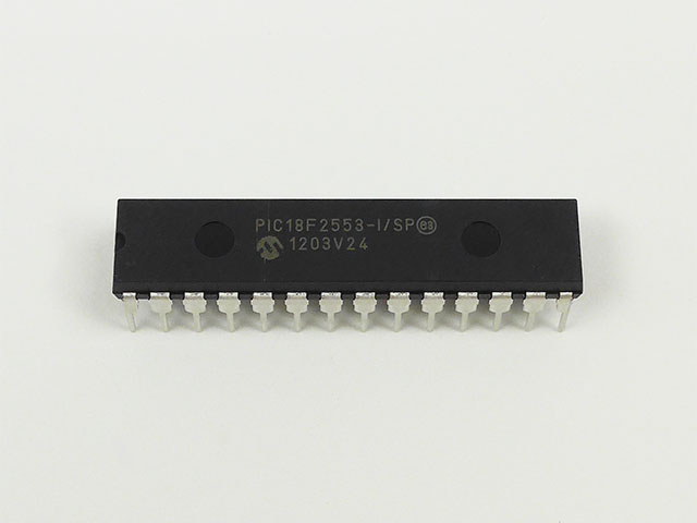
Microchip PIC18F2553 MCU heximal recovering can help engineer to restore embedded source code from secured microcontroller PIC18F2553 flash program memory and eeprom data memory, then engineer will be able to copy firmware binary file or heximal data to new microprocessor PIC18F2553;
The Timer1 oscillator should already be running prior to entering SEC_RUN mode which is necessary for Microchip PIC18F2553 MCU Heximal Recovering. If the T1OSCEN bit is not set when the SCS1:SCS0 bits are set to ‘01’, entry to SEC_RUN mode will not occur for Microchip PIC18F2520 Embedded Firmware Extraction. If the Timer1 oscillator is enabled, but not yet running, device clocks will be delayed until the oscillator has started. In such situa- tions, initial oscillator operation is far from stable and unpredictable operation may result.
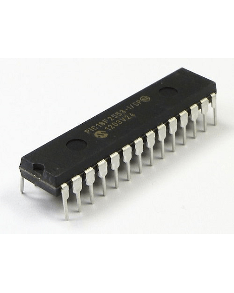
การกู้คืนเลขฐานสิบหกของ MCU ของ Microchip PIC18F2553 ช่วยให้วิศวกรสามารถกู้คืนรหัสต้นฉบับที่ฝังไว้จากหน่วยความจำโปรแกรมแฟลชของไมโครคอนโทรลเลอร์ PIC18F2553 ที่ปลอดภัยและหน่วยความจำข้อมูล EEPROM จากนั้นวิศวกรก็จะสามารถคัดลอกไฟล์ไบนารีของเฟิร์มแวร์หรือข้อมูลเลขฐานสิบหกไปยังไมโครโปรเซสเซอร์ PIC18F2553 ใหม่ได้
On transitions from SEC_RUN to PRI_RUN mode, the peripherals and CPU continue to be clocked from the Timer1 oscillator while the primary clock is started. When the primary clock becomes ready, a clock switch back to the primary clock occurs (see below Figure). When the clock switch is complete, the T1RUN bit is cleared, the OSTS bit is set and the primary clock is providing the clock to Microchip MCU PIC16F870 Heximal Code Restoration. The IDLEN and SCS bits are not affected by the wake-up; the Timer1 oscillator continues to run.
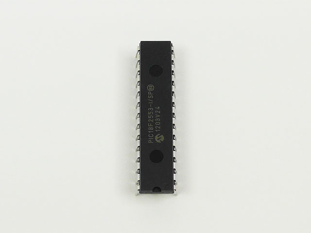
Восстановление шестнадцатеричных данных микроконтроллера Microchip PIC18F2553 может помочь инженеру восстановить встроенный исходный код из защищенной флэш-памяти программ микроконтроллера PIC18F2553 и памяти данных EEPROM, после чего инженер сможет скопировать двоичный файл прошивки или шестнадцатеричные данные на новый микропроцессор PIC18F2553;
In RC_RUN mode, the CPU and peripherals are clocked from the internal oscillator block using the INTOSC multiplexer. In this mode, the primary clock is shut down in order to Recover Freescale MCU MC9S12XDG128 Memory Program. When using the INTRC source, this mode provides the best power conservation of all the Run modes, while still executing code in the process of Microchip PIC18F2553 MCU Heximal Recovering. It works well for user applications which are not highly timing sensitive or do not require high-speed clocks at all times.
Microchip PIC18F2553 MCU Heximal Recovering
If the primary clock source is the internal oscillator block (either INTRC or INTOSC), there are no distinguishable differences between PRI_RUN and RC_RUN modes during MCU Crack execution. However, a clock switch delay will occur during entry to and exit from RC_RUN mode which can be carried out by Reverse Engineering Microchip PIC16F1913 Memory. Therefore, if the primary clock source is the internal oscillator block, the use of RC_RUN mode is not recommended.
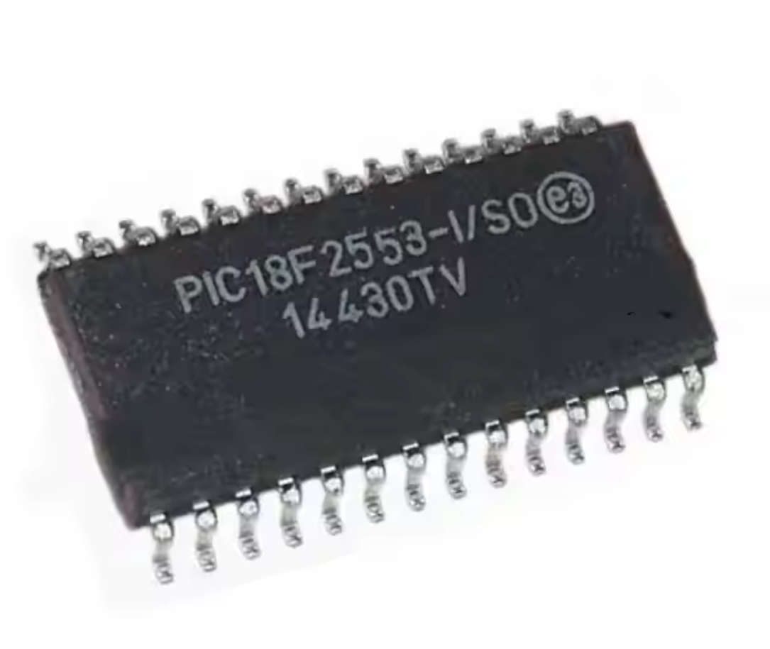
Phục hồi mã heximal MCU của Microchip PIC18F2553 có thể giúp kỹ sư khôi phục mã nguồn nhúng từ bộ nhớ chương trình flash và bộ nhớ dữ liệu eeprom của vi điều khiển được bảo mật PIC18F2553, sau đó kỹ sư sẽ có thể sao chép tệp nhị phân chương trình cơ sở hoặc dữ liệu heximal sang vi xử lý mới PIC18F2553;
Break Microchip PIC18F2553 Controller Protection
The power-managed mode that is invoked with the SLEEP instruction is determined by the setting of the IDLEN bit at the time the instruction is executed by Break Microchip PIC18F2553 Controller Protection. If another SLEEP instruction is executed, the device will enter the power-managed mode specified by IDLEN at that time. If IDLEN has changed, the device will enter the new power-managed mode specified by the new setting. Entry to, and exit from Idle mode, does not affect the state of the IDLEN bit.
In the Run modes, clocks to both the core and peripherals are active. The difference between these modes is the clock source. The PRI_RUN mode is the normal, full power execution mode of the microcontroller. This is also the default mode upon a device Reset, unless Two-Speed Start-up is enabled. In this mode, the OSTS bit is set. The IOFS bit may be set if the internal oscillator block is the primary clock source.
Break Microchip PIC18F2553 Controller Protection
The SEC_RUN mode is the compatible mode to the “clock switching” feature offered in other PIC18 devices. In this mode, the CPU and peripherals are clocked from the Timer1 oscillator. This gives users the option of lower power consumption while still using a high accuracy clock source.
SEC_RUN mode is entered by setting the SCS1:SCS0 bits to ‘01’. The device clock source is switched to the Timer1 oscillator (see Figure 3-1), the primary oscillator is shut down, the T1RUN bit (T1CON<6>) is set and the OSTS bit is cleared.
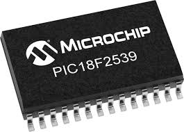
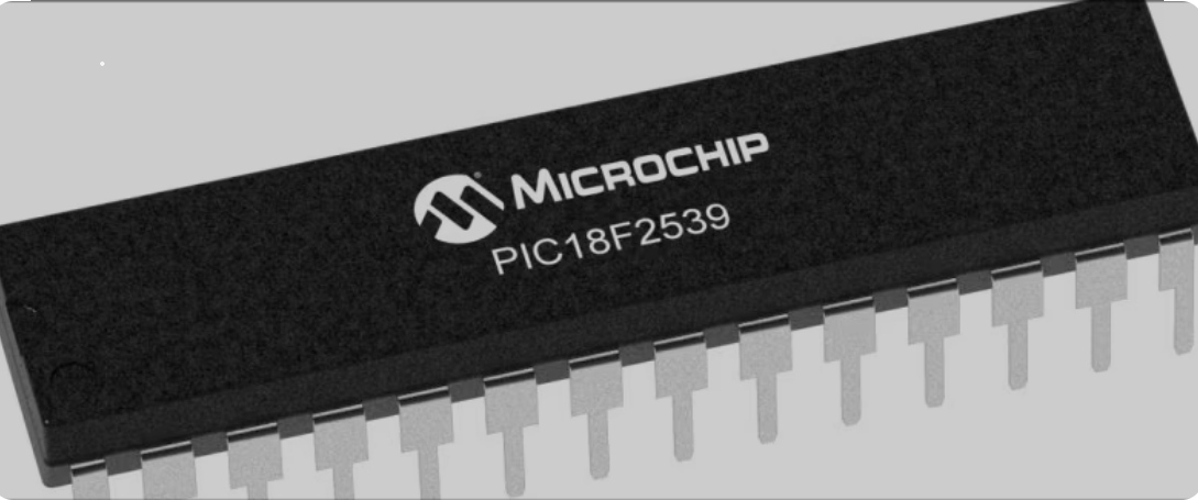
Recover PIC18F2539 Microcontroller Lost Heximal File
Recover PIC18F2539 microcontroller lost heximal file from original microchip MCU PIC18F2539 flash program memory and eeprom data memory, decrypt protective PIC18F2539 microprocessor’s security fuse bit and extract binary file or heximal source code from its embedded firmware;
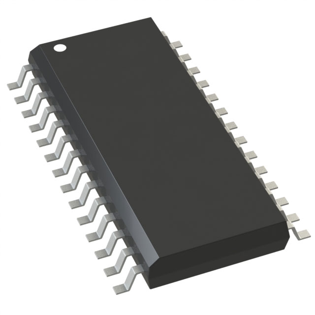
Recover PIC18F2539 microcontroller lost heximal file from original microchip MCU PIC18F2539 flash program memory and eeprom data memory, decrypt protective PIC18F2539 microprocessor’s security fuse bit and extract binary file or heximal source code from its embedded firmware;
The length of the transition between clock sources is the sum of two cycles of the old clock source by Recover PIC18F2539 Microcontroller Lost Heximal File and three to four cycles of the new clock source. This formula assumes that the new clock source is stable.
Three bits indicate the current clock source and its status. They are:
- OSTS (OSCCON<3>)
- IOFS (OSCCON<2>)
- T1RUN (T1CON<6>)
In general, only one of these bits will be set while in a given power-managed mode. When the OSTS bit is set, the primary clock is providing the device clock by Break Nuvoton W78E054 MCU Flash. When the IOFS bit is set, the INTOSC output is providing a stable 8 MHz clock source to a divider that actually drives the device clock.
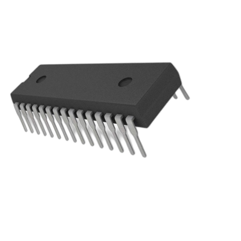
PIC18F2539 mikrodenetleyicisinin kaybolan heksimal dosyasını orijinal mikroçip MCU PIC18F2539 flaş program belleğinden ve eeprom veri belleğinden kurtarın, koruyucu PIC18F2539 mikroişlemcisinin güvenlik sigorta bitini şifresini çözün ve gömülü aygıt yazılımından ikili dosyayı veya heksimal kaynak kodunu çıkarın
When the T1RUN bit is set, the Timer1 oscillator is providing the clock. If none of these bits are set, then either the INTRC clock source is clocking the device, or the INTOSC source is not yet stable after Crack MCU Memory.
Recover PIC18F2539 Microcontroller Lost Heximal File
If the internal oscillator block is configured as the primary clock source by the FOSC3:FOSC0 Configuration bits in order to Attack Winbond W78E051A Protected Eeprom, then both the OSTS and IOFS bits may be set when in PRI_RUN or PRI_IDLE modes. This indicates that the primary clock (INTOSC output) is generating a stable 8 MHz output from Recover PIC18F2539 Microcontroller Lost Heximal File. Entering another power-managed RC mode at the same frequency would clear the OSTS bit.
recuperați fișierul heximal pierdut al microcontrolerului PIC18F2539 din memoria programului flash original al microcipului MCU PIC18F2539 și memoria de date eeprom, decriptați bitul siguranței de securitate al microprocesorului PIC18F2539 și extrageți fișierul binar sau codul sursă heximal din firmware-ul său încorporat
Caution should be used when modifying a single IRCF bit through Reverse Engineering W78E52B Chip Data. If VDD is less than 3V, it is possible to select a higher clock speed than is supported by the low VDD. Improper device operation may result if the VDD/FOSC specifications are violated.
Executing a SLEEP instruction does not necessarily place the device into Sleep mode. It acts as the trigger to place the controller into either the Sleep mode or one of the Idle modes, depending on the setting of the IDLEN bit for the purpose of Winbond Microcontroller W78E0516 Embedded Binary Recovering.
récupérer le fichier hexadécimal perdu du microcontrôleur PIC18F2539 de la mémoire de programme flash PIC18F2539 et de la mémoire de données EEPROM d’origine du microprocesseur MCU PIC18F2539, décrypter le bit de fusible de sécurité du microprocesseur PIC18F2539 et extraire le fichier binaire ou le code source hexadécimal de son micrologiciel intégré
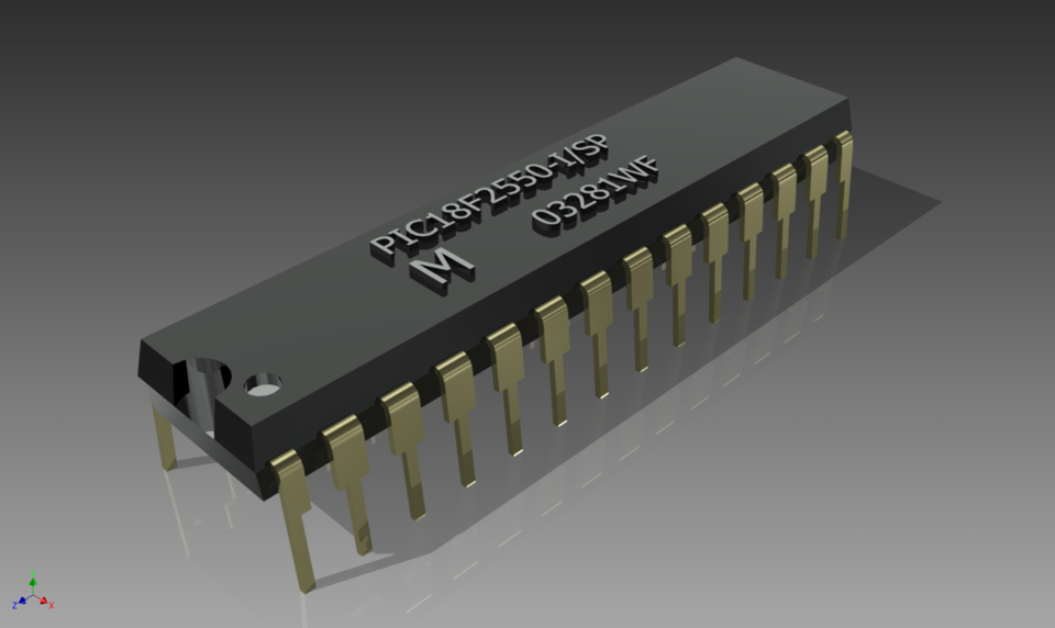
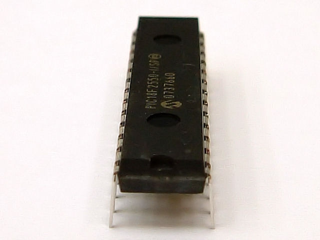
Break Microchip PIC18F2550 MCU Memory
Break Microchip PIC18F2550 MCU memory and restore encrypted microcontroller PIC18F2550’s embedded firmware in the format of binary file or heximal data, through reverse engineering technique to crack down the protective system of locked microprocessor PIC18F2550;
break Microchip PIC18F2550 MCU memory and restore encrypted microcontroller PIC18F2550’s embedded firmware in the format of binary file or heximal data, through reverse engineering technique to crack down the protective system of locked microprocessor PIC18F2550;
PIC18F2550 devices offer a total of seven operating modes for more efficient power management by Crack MCU Firmware. These modes provide a variety of options for selective power conservation in applications where resources may be limited and Break Microchip PIC18F2550 MCU Memory (i.e., battery-powered devices).
There are three categories of power-managed modes:
• Run modes
• Idle modes
• Sleep mode
These categories define which portions of the device are clocked and sometimes, what speed. The Run and Idle modes may use any of the three available clock sources when Attack Microchip PIC18F2525 Processor Memory (primary, secondary or internal oscillator block). The Sleep mode does not use a clock source.
The power-managed modes include several power- saving features offered on previous PIC® devices.
Kilitli mikroişlemci PIC18F2550’nin koruyucu sistemini çökertmek için tersine mühendislik tekniği kullanarak Microchip PIC18F2550 MCU belleğini kırın ve şifrelenmiş mikrodenetleyici PIC18F2550’nin gömülü aygıt yazılımını ikili dosya veya onaltılık veri biçiminde geri yükleyin;
One is the clock switching feature, offered in other PIC18 devices, allowing the controller to use the Timer1 oscillator in place of the primary oscillator to facilitate the process of Reverse Engineering PIC18F2520 Controller. Also included is the Sleep mode, offered by all PIC devices, where all device clocks are stopped.
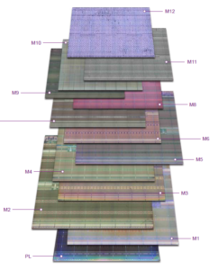
Break Microchip PIC18F2550 MCU Memory
Selecting a power-managed mode requires two decisions: if the CPU is to be clocked or not and the selection of a clock source. The IDLEN bit (OSCCON<7>) controls CPU clocking, while the SCS1:SCS0 bits (OSCCON<1:0>) select the clock source for the purpose of Break PIC18F2523 CPU Memory. The individual modes, bit settings, clock sources and affected modules are summarized in below Table.
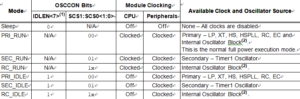
The SCS1:SCS0 bits allow the selection of one of three clock sources for power-managed modes.
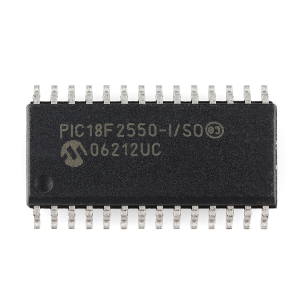
sparge memoria Microchip PIC18F2550 MCU și restaura firmware-ul încorporat al microcontrolerului criptat PIC18F2550 în format de fișier binar sau date heximale, prin tehnica de inginerie inversă pentru a distruge sistemul de protecție al microprocesorului blocat PIC18F2550;
They are: the primary clock, as defined by the FOSC3:FOSC0 Configuration bits to Microprocessor PIC18F2515 Heximal File Recovery
the secondary clock (the Timer1 oscillator)
the internal oscillator block (for RC modes)
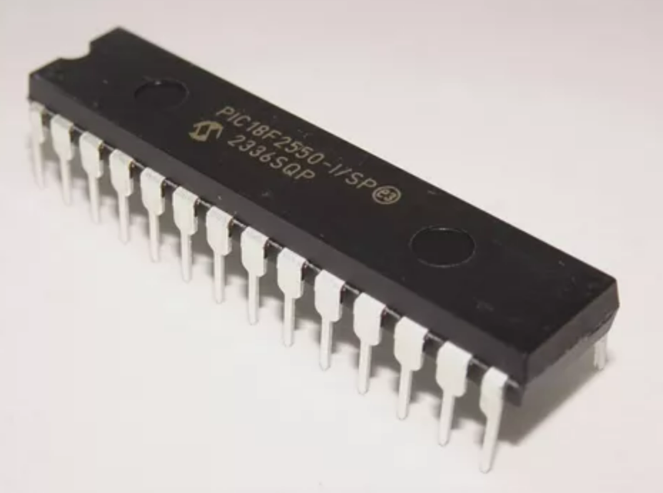
briser la mémoire du microcontrôleur Microchip PIC18F2550 et restaurer le micrologiciel intégré crypté du microcontrôleur PIC18F2550 au format de fichier binaire ou de données hexadécimales, grâce à une technique d’ingénierie inverse pour déchiffrer le système de protection du microprocesseur verrouillé PIC18F2550 ;