 Recover IC PIC16F873 Heximal
 May 26th, 2000 |
  Author:
 The Microchip PIC16F873 is a widely used 8-bit microcontroller in industrial, automotive, and consumer electronics applications. Known for its reliability, low power consumption, and integrated peripherals, it is often deployed in embedded systems where firmware is stored in flash memory and EEPROM. Many of these systems are protected, locked, or even encrypted to safeguard intellectual property. However, when original firmware is lost, damaged, or inaccessible, users face the critical challenge of retrieving the heximal file to restore normal functionality.
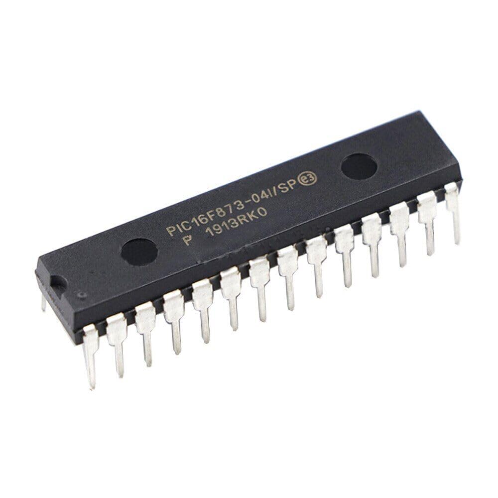
At CIRCUIT ENGINEERING CO., LTD, we specialize in Recover IC PIC16F873 Heximal services. Our engineering team has the expertise to unlock, crack, hack, decode, and decrypt even secured PIC16F873 devices, enabling clients to regain access to valuable binary and source code data stored in their program memory or EEPROM.
Our Recovery Process
- Secure Device Handling – We begin with careful examination of the IC to ensure no physical damage occurs during extraction.
- Firmware Access Techniques – Using advanced hardware interfaces and proprietary methods, we can open protected microcontrollers and bypass security measures without harming the device.
- Heximal File Extraction – The recovered firmware is output in heximal format, which can be directly re-programmed into a replacement chip or used for further analysis.
- Optional Disassembly – Upon request, we can copy, clone, or duplicate the extracted program into other compatible PIC devices, or reverse-engineer it into readable source code for development purposes.
Applications of PIC16F873
The PIC16F873 is popular in:
- Industrial control systems – managing sensors, motors, and process automation.
- Automotive electronics – supporting dashboard controls, security modules, and diagnostic systems.
- Consumer devices – from household appliances to small gadgets requiring reliable microcontroller performance.
- Communication equipment – handling protocol conversion, signal processing, and embedded messaging systems.
Its integrated flash memory, on-chip EEPROM, and low-power architecture make it ideal for long-term deployments where updates are rare but reliability is essential.
Why Choose Our Service
- Technical Expertise – Years of hands-on experience with Microchip devices ensures we can deal with both old and modern protection schemes.
- Advanced Tools – We employ precision hardware programmers, fault-injection systems, and firmware analysis software to achieve high recovery success rates.
- Confidentiality Guaranteed – All data, files, and archives are handled with strict non-disclosure protocols.
- Custom Solutions – Whether your goal is to restore a failed device, duplicate a working program, or conduct in-depth firmware analysis, we tailor our process to meet your needs.
Conclusion
Losing firmware from a secured PIC16F873 microcontroller can halt operations, cause costly downtime, and threaten product continuity. Our Recover IC PIC16F873 Heximal service is designed to give you back control — quickly, safely, and with full technical support. By recovering and restoring your heximal file, we ensure your systems stay operational and your investment in embedded technology remains protected.
If you need professional assistance to recover, unlock, or restore your PIC16F873 firmware, contact CIRCUIT ENGINEERING CO., LTD today for a secure and effective solution.
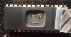
Recover IC PIC16F873 Heximal out from Microcontroller PIC16F873 secured memory, remove the protection over MCU PIC16F873 by Unlocking microcontroller security fuse bit, and readout the firmware from MCU flash memory;
Devices Included in this Data Sheet:
Analog Features:
· 10-bit, up to 8-channel Analog-to-Digital Converter (A/D)
· Brown-out Reset (BOR)
High-Performance RISC CPU:
· Only 35 single-word instructions to learn
· All single-cycle instructions except for program branches, which are two-cycle
· Operating speed: DC – 20 MHz clock input DC – 200 ns instruction cycle
· Up to 8K x 14 words of Flash Program Memory,
Up to 368 x 8 bytes of Data Memory (RAM),
Up to 256 x 8 bytes of EEPROM Data Memory
· Pinout compatible to other 28-pin or 40/44-pin PIC16CXXX and PIC16FXXX microcontrollers
Peripheral Features:
· Timer0: 8-bit timer/counter with 8-bit prescaler
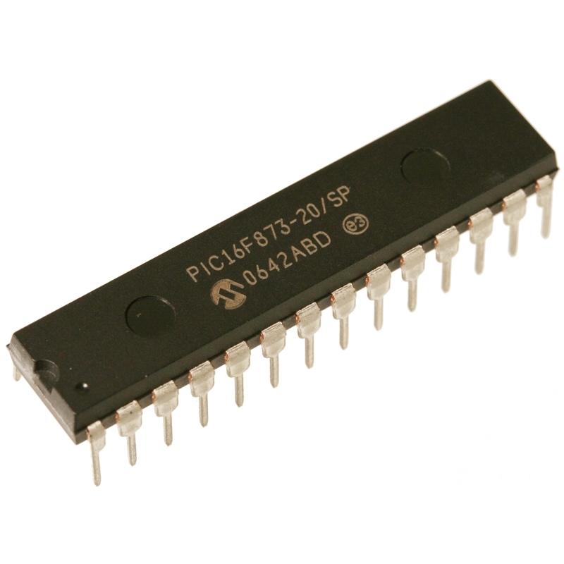
decrypt locked mcu PIC16F873 flash memory and extract embedded firmware from flash memory
· Timer1: 16-bit timer/counter with prescaler, can be incremented during Sleep via external crystal/clock
· Timer2: 8-bit timer/counter with 8-bit period register, prescaler and postscaler
· Two Capture, Compare, PWM modules
– Capture is 16-bit, max. resolution is 12.5 ns
– Compare is 16-bit, max. resolution is 200 ns
– PWM max. resolution is 10-bit
· Synchronous Serial Port (SSP) with SPI™ (Master mode) and I2C™ (Master/Slave)
· Universal Synchronous Asynchronous Receiver Transmitter (USART/SCI) with 9-bit address detection
· Parallel Slave Port (PSP) – 8 bits wide with external RD, WR and CS controls (40/44-pin only)
· Brown-out detection circuitry for Brown-out Reset (BOR)
· Analog Comparator module with:
– Two analog comparators
– Programmable on-chip voltage reference (VREF) module
– Programmable input multiplexing from device inputs and internal voltage reference
– Comparator outputs are externally accessible
Special Microcontroller Features:
· 100,000 erase/write cycle Enhanced Flash program memory typical
· 1,000,000 erase/write cycle Data EEPROM memory typical
· Data EEPROM Retention > 40 years
· Self-reprogrammable under software control
· In-Circuit Serial Programming™ (ICSP™) via two pins
· Single-supply 5V In-Circuit Serial Programming
· Watchdog Timer (WDT) with its own on-chip RC oscillator for reliable operation
· Programmable code protection
· Power saving Sleep mode
· Selectable oscillator options
· In-Circuit Debug (ICD) via two pins CMOS Technology:
· Low-power, high-speed Flash/EEPROM technology
· Fully static design
· Wide operating voltage range (2.0V to 5.5V)
· Commercial and Industrial temperature ranges
· Low-power consumption
 Posted in Recover Chip |
  Tags: капіраваць encrypted mcu binary, капіраваць encrypted mcu code, капіраваць encrypted mcu data, капіраваць encrypted mcu eeprom, капіраваць encrypted mcu file, капіраваць encrypted mcu firmware, капіраваць encrypted mcu flash, капіраваць encrypted mcu heximal, капіраваць encrypted mcu memory, капіраваць encrypted mcu program |
  Comments Closed
Copy MCU PIC18F4685 Software
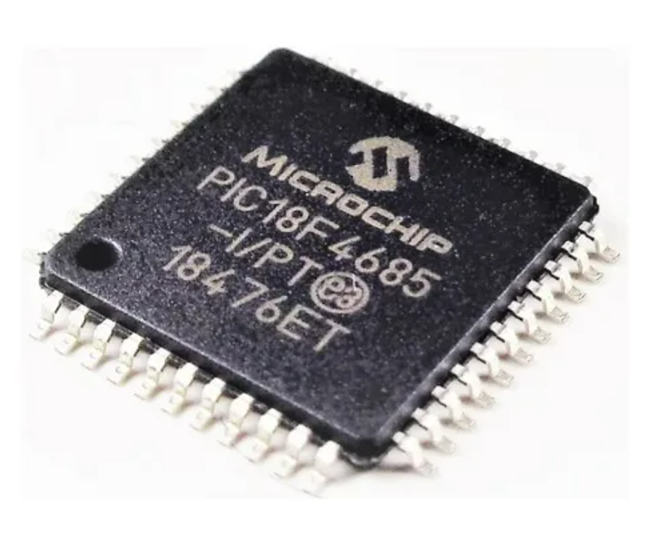
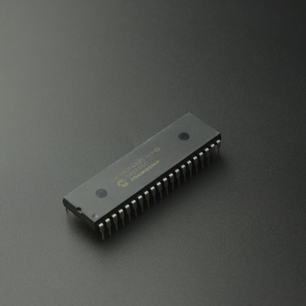
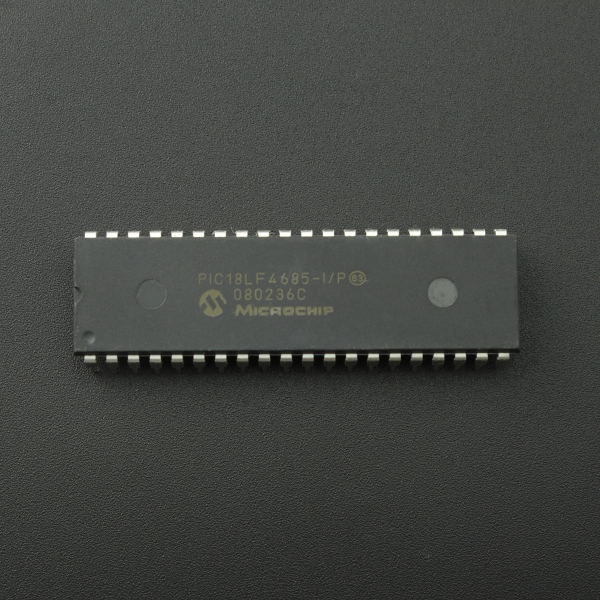
The PIC18F4685 is a powerful 8-bit microcontroller from Microchip Technology, widely adopted in automotive electronics, industrial control systems, smart devices, and other advanced embedded applications. Designed with integrated CAN communication, extended EEPROM capabilities, and a large program flash memory, this chip is known for its high-performance, secured architecture and robust data protection mechanisms.
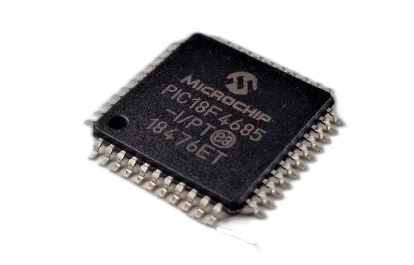
However, when the original heximal or binary files are lost or inaccessible, it can bring development or maintenance to a standstill. Whether for legacy system restoration, product optimization, or technical auditing, customers may find themselves needing to copy MCU PIC18F4685 software from a functional device. This task can be daunting due to the chip’s locked, encrypted, or code-protected memory structure.
That’s where [Your Company Name] comes in.
Specialized Service to Recover PIC18F4685 Firmware
We provide professional, confidential services to copy, clone, or duplicate the complete contents of the MCU PIC18F4685, including program flash, EEPROM, and configuration data. Whether the device is secured, obfuscated, or encrypted, our team utilizes sophisticated hardware interfaces and reverse engineering techniques to unlock, crack, or decode the protected firmware without damaging the chip.
Through a series of non-destructive probing, memory readout, and firmware extraction processes, we can help you recover the essential heximal files, source code, or data archives needed for:
- Software backup and replication
- Faulty device replacement
- Legacy product updates
- Custom modification or migration
- Vulnerability assessment and debugging
Why the PIC18F4685 Stands Out
This Microchip MCU offers advanced features that make it ideal for complex control systems:
- 96KB of Flash program memory and 1KB EEPROM, suitable for multi-function codebases
- Integrated Enhanced CAN module for robust communication in automotive or industrial networks
- 10-bit ADC, PWM modules, and multiple timers for flexible peripheral control
- Self-write programming capability, enabling field updates
- Selective code protection to prevent unauthorized access
These features make the PIC18F4685 highly reliable but also difficult to access once the firmware is locked. This level of protection is excellent for manufacturers but presents a challenge when legitimate recovery is needed.
What We Deliver
Our service doesn’t just copy or clone memory—we deliver meaningful, usable output. You receive a verified heximal firmware file, and upon request, we can assist in disassembling or partially reverse-engineering the binary to a more human-readable form, such as assembly or annotated code.
Clients trust us for our discretion, deep technical knowledge, and ethical approach. We handle each case individually, ensuring your data and objectives remain secure throughout the process.
Conclusion
If you’re in a situation where you need to restore, decrypt, or recover a protected program file from a PIC18F4685, don’t take chances with unreliable tools or guesswork. Let our experts help you copy MCU PIC18F4685 software professionally, with accuracy and respect for your IP needs. Contact us today to learn how we can support your embedded system goals.
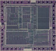
Copy MCU PIC18F4685 software inside microcontroller PIC18F4685 flash memory, decapsulate silicon package of microcontroller and get its fuse bit exposed, so MCU cracking technique will be able to reset the bit and readout the firmware from Microcontroller;
Power-Managed Modes:
Peripheral Highlights:
Run: CPU on, peripherals on
Idle: CPU off, peripherals on
Sleep: CPU off, peripherals off
Idle mode currents down to 5.8 ìA typical
Sleep mode currents down to 0.1 ìA typical
Timer1 Oscillator: 1.1 ìA, 32 kHz, 2V
Watchdog Timer: 2.1 ìA
Two-Speed Oscillator Start-up
High-Current Sink/source 25 mA/25 mA
Three External Interrupts
One Capture/Compare/PWM (CCP1) module
Enhanced Capture/Compare/PWM (ECCP1) module
(40/44-pin devices only):
– One, two or four PWM outputs
– Selectable polarity
– Programmable dead time
Flexible Oscillator Structure:
· Four Crystal modes, up to 40 MHz
· 4x Phase Lock Loop (PLL) – available for crystal and internal oscillators
· Two External RC modes, up to 4 MHz
· Two External Clock modes, up to 40 MHz
· Internal Oscillator Block:
– 8 user-selectable frequencies, from 31 kHz to 8 MHz
– Provides a complete range of clock speeds,
from 31 kHz to 32 MHz when used with PLL
– User-tunable to compensate for frequency drift
· Secondary Oscillator using Timer1 @ 32 kHz
· Fail-Safe Clock Monitor
– Allows for safe shutdown if peripheral clock stops
– Auto-shutdown and auto-restart
Master Synchronous Serial Port (MSSP) module supporting 3-Wire SPI (all 4 modes) and I2C™
Master and Slave modes
Enhanced Addressable USART module:
– Supports RS-485, RS-232 and LIN 1.3
– RS-232 operation using internal oscillator block (no external crystal required)
– Auto-wake-up on Start bit
– Auto-Baud Detect
10-Bit, up to 11-Channel Analog-to-Digital
Converter module (A/D), up to 100 ksps:
– Auto-acquisition capability
– Conversion available during Sleep
Dual Analog Comparators with Input Multiplexing
Special Microcontroller Features:
· C compiler Optimized Architecture with optional
Extended Instruction Set
· 100,000 Erase/Write Cycle Enhanced Flash
Program Memory typical
· 1,000,000 Erase/Write Cycle Data EEPROM
Memory typical
· Flash/Data EEPROM Retention: > 40 years
· Self-Programmable under Software Control
· Priority Levels for Interrupts
· 8 x 8 Single-Cycle Hardware Multiplier
· Extended Watchdog Timer (WDT):
– Programmable period from 41 ms to 131s
· Single-Supply 5V In-Circuit Serial
Programming™ (ICSP™) via two pins
· In-Circuit Debug (ICD) via two pins
· Wide operating voltage range: 2.0V to 5.5V
ECAN Module Features:
· Message bit rates up to 1 Mbps
· Conforms to CAN 2.0B ACTIVE Specification
· Fully Backward Compatible with PIC18XXX8 CAN modules
· Three Modes of Operation:
– Legacy, Enhanced Legacy, FIFO
· Three Dedicated Transmit Buffers with Prioritization
· Two Dedicated Receive Buffers
· Six Programmable Receive/Transmit Buffers
· Three Full, 29-Bit Acceptance Masks
· 16 Full, 29-Bit Acceptance Filters w/Dynamic Association
· DeviceNet™ Data Byte Filter Support
· Automatic Remote Frame Handling
· Advanced Error Management Features
Reverse IC ATmega861V Code
Reverse IC ATmega861V code programming process, disable the protective measurement by unlock microcontroller ATmega861V, extract content from MCU program memory and reprogramme the firmware to new ATmega861V;
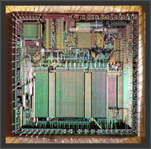
Reverse IC ATmega861V code programming process, disable the protective measurement by unlock microcontroller ATmega861V, extract content from MCU program memory and reprogramme the firmware to new ATmega861V
The Compare Output mode (COM2x1:0) bits have two functions. The Waveform Generator uses the COM2x1:0 bits for defining the Output Compare (OC2x) state at the next compare match.
Also, the COM2x1:0 bits control the OC2x pin output source. Figure 70 shows a simplified schematic of the logic affected by the COM2x1:0 bit setting. The I/O Registers, I/O bits, and I/O pins in the figure are shown in bold. Only the parts of the general I/O Port Control Registers (DDR and PORT) that are affected by the COM2x1:0 bits are shown if breaking Microcontroller PIC16C65B eeprom.
When referring to the OC2x state, the reference is for the internal OC2x Register, not the OC2x pin. The general I/O port function is overridden by the Output Compare (OC2x) from the Waveform Generator if either of the COM2x1:0 bits are set.
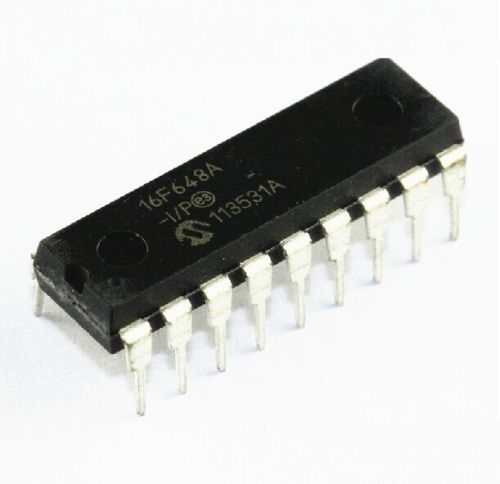
decode microprocessor PIC16F648A flash memory and extract heximal data from its memory
However, the OC2x pin direction (input or output) is still controlled by the Data Direction Register (DDR) for the port pin. The Data Direction Register bit for the OC2x pin (DDR_OC2x) must be set as output before the OC2x value is visible on the pin. The port override function is independent of the Waveform Generation mode.
The design of the Output Compare pin logic allows initialization of the OC2x state before the output is enabled. Note that some COM2x1:0 bit settings are reserved for certain modes of operation. See “8-bit Timer/Counter Register Description” on page 184 if Recover MCU PIC16F687 software code.
The Waveform Generator uses the COM2x1:0 bits differently in normal, CTC, and PWM modes. For all modes, setting the COM2x1:0 = 0 tells the Waveform Generator that no action on the OC2x Register is to be performed on the next compare match.
For compare output actions in the non-PWM modes refer to Table 88 on page 185. For fast PWM mode, refer to Table 89 on page 185, and for phase correct PWM refer to Table 90 on page 186. A change of the COM2x1:0 bits state will have effect at the first compare match after the bits are written. For non-PWM modes, the action can be forced to have immediate effect by using the FOC2x strobe bits.
Recover MCU PIC16F648A Firmware
Recover MCU PIC16F648A Firmware from microcontroller PIC16F648A flash memory is the result of MCU cracking, after application of this technique over the master MCU PIC16F648A with original program into it;
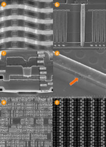
Recover MCU PIC16F648A Firmware from microcontroller PIC16F648A flash memory is the result of MCU cracking, after application of this technique over the master MCU PIC16F648A with original program into it
A variety of frequency ranges and packaging options are available. Depending on application and production requirements, the proper device option can be selected using the information in the PIC16F648A Product Identification System, at the end of this data sheet. When placing orders, please use this page of the data sheet to specify the correct part number.
FLASH Devices
FLASH devices can be erased and re-programmed electrically. This allows the same device to be used for prototype development, pilot programs and production. A further advantage of the electrically erasable FLASH is that it can be erased and reprogrammed in-circuit, or by device programmers, such as Microchip’s PICSTART® Plus, or PRO MATE® II programmers.
Quick-Turnaround-Production
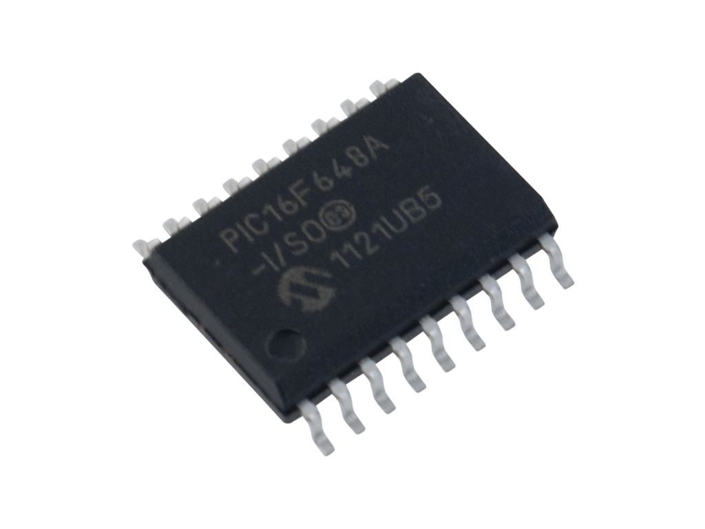
Break PIC16F648A microprocessor protection and readout firmware program from flash memory
(QTP) Devices Microchip offers a QTP Programming Service for factory production orders. This service is made available for users who chose not to program a medium to high quantity of units and whose code patterns have stabilized. The devices are standard FLASH devices but with all program locations and configuration options already programmed by the factory. Certain code and prototype verification procedures apply before production shipments are available. Please contact your Microchip Technology sales office for more details.
Serialized Quick-Turnaround Production (SQTPSM) Devices
Microchip offers a unique programming service where a few user-defined locations in each device are programmed with different serial numbers. The serial numbers may be random, pseudo-random or sequential. Serial programming allows each device to have a unique number, which can serve as an entry-code, password or ID number
Recover PIC MCU Microchip 16LF506 Firmware
Recover PIC MCU Microchip 16LF506 Firmware and copy program to new Microcontroller PIC16LF506, clone master PIC16LF506 mcu which can provide the same functions as original master Microprocessor;
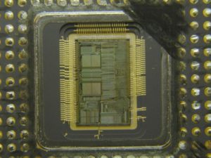
Recover PIC MCU Microchip 16LF506 Firmware and copy program to new Microcontroller PIC16LF506, clone master PIC16LF506 mcu which can provide the same functions as original master Microprocessor
Data memory is composed of registers or bytes of RAM. Therefore, data memory for a device is specified by its register file. The register file is divided into two functional groups: Special Function Registers (SFR) and General Purpose Registers (GPR).
The Special Function Registers include the TMR0 register, the Program Counter (PCL), the STATUS register, the I/O registers (ports) and the File Select Register (FSR). In addition, Special Function Registers are used to control the I/O port configuration and prescaler options when Recover IC STM32F107RCT6 code.
The General Purpose Registers are used for data and control information under command of the instructions. For the PIC12F510, the register file is composed of 10 Special Function Registers, 6 General Purpose.
Registers and 32 General Purpose Registers accessed For the PIC16F506, the register file is composed of 13 Special Function Registers, 3 General Purpose Registers and 64 General Purpose Registers accessed.
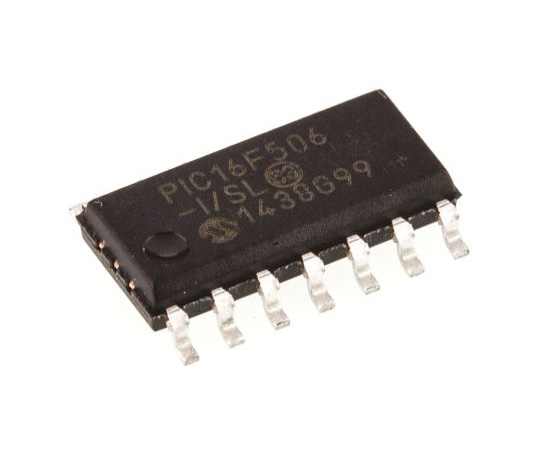
unlock microcontroller PIC16F506 tamper resistance system and extract embedded program data from flash memory
The Special Function Registers (SFRs) are registers used by the CPU and peripheral functions to control the operation of the device (see Table 4-1).
The Special Function Registers can be classified into two sets. The Special Function Registers associated with the “core” functions are described in this section for the purpose of chip AT89S8252 flash content copying.
Those related to the operation of the peripheral features are described in the section for each peripheral feature.
This register contains the arithmetic status of the ALU, the Reset status and the page preselect bit.
The STATUS register can be the destination for any instruction, as with any other register. If the STATUS register is the destination for an instruction that affects the Z, DC or C bits, then the write to these three bits is disabled. These bits are set or cleared according to the device logic. Furthermore, the TO and PD bits are not writable. Therefore, the result of an instruction with the STATUS register as destination may be different than intended.
For example, CLRF STATUS, will clear the upper three bits and set the Z bit. This leaves the STATUS register
as 000u u1uu (where u = unchanged).
Therefore, it is recommended that only BCF, BSF and MOVWF instructions be used to alter the STATUS register. These instructions do not affect the Z, DC or C bits from the STATUS register. For other instructions which do affect Status bits.