Archive for August, 2018
 Copy PIC18F2480 MCU Locked Heximal
Using the internal oscillator as the clock source eliminates the need for up to two external oscillator pins when Crack MCU Firmware, which can then be used for digital I/O and Copy PIC18F2480 MCU Locked Heximal. Two distinct configurations are available:
- In INTIO1 mode, the OSC2 pin outputs FOSC/4, while OSC1 functions as RA7 for digital input and output.
- In INTIO2 mode, OSC1 functions as RA7 and OSC2 functions as RA6, both for digital input and output.
The internal oscillator block is calibrated at the factory to produce an INTOSC output frequency of 8.0 MHz when Recover Atmel AVR Controller ATmega48V Firmware.
The INTRC oscillator operates independently of the INTOSC source. Any changes in INTOSC across voltage and temperature are not necessarily reflected by changes in INTRC and vice versa.
Copy PIC18F2480 MCU Locked Heximal
The internal oscillator’s output has been calibrated at the factory but can be adjusted in the user’s applica- tion. This is done by writing to the OSCTUNE register from Break Atmel AVR MCU ATmega8535L Heximal.
When the OSCTUNE register is modified, the INTOSC frequency will begin shifting to the new frequency. The INTOSC clock will stabilize within 1 ms. Code execu- tion continues during this shift after Break IC ATmega88V Internal Flash. There is no indication that the shift has occurred.
The OSCTUNE register also implements the INTSRC and PLLEN bits, which control certain features of the internal oscillator block. The INTSRC bit allows users to select which internal oscillator provides the clock source when the 31 kHz frequency option is selected when Restore Microprocessor Program Most Important Two Steps. This is covered in greater detail in Section 2.7.1 “Oscillator Control Register”. The PLLEN bit controls the operation of the frequency multiplier, PLL, in Internal Oscillator modes.
Losted PIC18F2458 Microcontroller Embedded Code Restoration
Without the back-up embedded firmware from microcontrollers sometimes could become the disaster for a company which try to rescue the obselete or not-produce-anymore devices, through our techniques, Losted PIC18F2458 Microcontroller Embedded Code Restoration process will help you get the firmware back from original PIC18F2458:
The HSPLL mode makes use of the HS mode oscillator for frequencies up to 10 MHz. A PLL then multiplies the oscillator output frequency by 4 to produce an internal clock frequency up to 40 MHz. The PLLEN bit is not available in this oscillator mode before Microchip PIC18F2520 Embedded Firmware Extraction.
The PLL is only available to the crystal oscillator when the FOSC3:FOSC0 Configuration bits are programmed for HSPLL mode (= 0110).
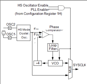
PLL BLOCK DIAGRAM
The PLL is also available to the internal oscillator block when the INTOSC is configured as the primary clock source from Microchip MCU PIC16F870 Heximal Code Restoration. In this configuration, the PLL is enabled in soft- ware and generates a clock output of up to 32 MHz.
The PIC18LF2458 devices include an internal oscillator block which generates two different clock signals; either can be used as the micro- controller’s clock source. This may eliminate the need for external oscillator circuits on the OSC1 and/or OSC2 pins in order to Recover Freescale MCU MC9S12XDG128 Memory Program.
The main output (INTOSC) is an 8 MHz clock source, which can be used to directly drive the device clock. It also drives a postscaler, which can provide a range of clock frequencies from 31 kHz to 4 MHz. The INTOSC output is enabled when a clock frequency from 125 kHz to 8 MHz is selected, and can provide 31 kHz if required.
Losted PIC18F2458 Microcontroller Embedded Code Restoration
The other clock source is the internal RC oscillator (INTRC) which provides a nominal 31 kHz output after Reverse Engineering Microchip PIC16F1913 Memory. INTRC is enabled if it is selected as the device clock source; it is also enabled automatically when any of the following are enabled:
• Power-up Timer
• Fail-Safe Clock Monitor
• Watchdog Timer
These features are discussed in greater detail in Section 23.0 “Special Features of the CPU”.
The clock source frequency (INTOSC direct, INTRC direct or INTOSC postscaler) is selected by configuring the IRCF bits of the OSCCON register before Unlock Microcontroller Flash. Additionally, the 31 kHz clock can be provided by either the INTOSC, or INTRC clock sources, depending on the INTSRC bit (OSCTUNE<7>).
Recover Microchip PIC18F2455 Memory Program
As one of the most important components to Recover Microchip PIC18F2455 Memory Program, for timing insensitive applications, the “RC” and “RCIO” device options offer additional cost savings. The actual oscillator frequency is a function of several factors:
• supply voltage
• values of the external resistor (REXT) and capacitor (CEXT)
• operating temperature
Given the same device, operating voltage and temperature and component values, there will also be unit-to-unit frequency variations before Recover PIC MCU Microchip PIC16LF506 Firmware. These are due to factors such as:
• normal manufacturing variation
• difference in lead frame capacitance between package types (especially for low CEXT values)
• variations within the tolerance of limits of REXT and CEXT
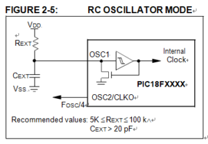
In the RC Oscillator mode, the oscillator frequency divided by 4 is available on the OSC2 pin when Decrypt Microchip PIC18F2321 MCU Heximal File. This signal may be used for test purposes or to synchronize other logic after Recover PIC MCU Microchip 12F510 Firmware. Below Figure shows how the R/C combination is connected.
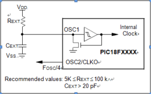
RC Oscillator Mode
The RCIO Oscillator mode (below Figure) functions like the RC mode, except that the OSC2 pin becomes an additional general purpose I/O pin. The I/O pin becomes bit 6 of PORTA (RA6).
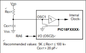
RCIO OSCILLATOR MODE in Recover Microchip PIC18F2455 Memory Program
A Phase Locked Loop (PLL) circuit is provided as an option for users who wish to use a lower frequency oscillator circuit, or to clock the device up to its highest rated frequency from a crystal oscillator after Copy Encrypted Microchip PIC18F2330 Heximal. This may be useful for customers who are concerned with EMI due to high-frequency crystals, or users who require higher clock speeds from an internal oscillator if the Microcontroller unlocking is completed.
Break PIC18F2450 Microcontroller Locked Heximal
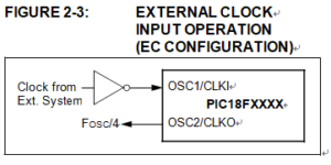
The EC and ECIO Oscillator modes require an external clock source to be connected to the OSC1 pin. There is no oscillator start-up time required after a Power-on Reset or after Break PIC18F2450 Microcontroller Locked Heximal. In the EC Oscillator mode, the oscillator frequency divided by 4 is available on the OSC2 pin. This signal may be used for test purposes or to synchronize other logic. Below Figure shows the pin connections for the EC Oscillator mode.
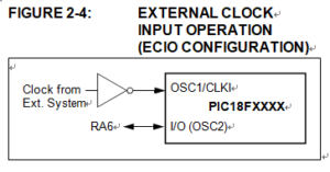
The ECIO Oscillator mode functions like the EC mode, except that the OSC2 pin becomes an additional general purpose I/O pin when Clone IC program. The I/O pin becomes bit 6 of PORTA (RA6). Figure 2-4 shows the pin connections for the ECIO Oscillator mode.
For timing insensitive applications, the “RC” and “RCIO” device options offer additional cost savings. The actual oscillator frequency is a function of several factors:
- supply voltage
- values of the external resistor (REXT) and capacitor (CEXT)
- operating temperature
Break PIC18F2450 Microcontroller Locked Heximal
Given the same device, operating voltage and temperature and component values, there will also be unit-to-unit frequency variations. These are due to factors such as:
- normal manufacturing variation
- difference in lead frame capacitance between package types (especially for low CEXT values)
- variations within the tolerance of limits of REXT and CEXT
In the RC Oscillator mode, the oscillator frequency divided by 4 is available on the OSC2 pin. This signal may be used for test purposes or to synchronize other logic. Figure 2-5 shows how the R/C combination is connected.