Posts Tagged ‘break microcontroller embedded firmware’
 Break Microcontroller NEC UPD78F0881 Software
 March 30th, 2014 |
  Author:
 We can break Microcontroller Chip NEC UPD78F0881, please view below the integrated circuit features for your reference:
Item
µPD78F0828A
µPD780828A
µPD780826A
ROM
59.5 Kbytes
Flash EE
60 Kbytes
Mask ROM
48 Kbytes
Mask ROM
32 Kbytes after break Microcontroller
Mask ROM
Hi-speed RAM
1024 bytes
Expansion RAM
2016 bytes
480 bytes
28 bytes
Memory space
64 Kbytes
General register
8 bits – 32 registers (8 bit x 8 x 4 bank)
Main system clock
0.25 µs/0.5 µs/1 µs/2 µs/4 µs (at 8 MHz) Instruction set when break Microcontroller
· 16-bit operation
· Multiplication/division (8 bits × 8 bits, 16 bits ÷ 8 bits)
· Bit manipulation (set, reset, test, boolean operation)
· BCD adjustment, etc.
I/O port
59 in total
Input ports: 5
Output ports: 16
I/O ports: 38
A/D converter
8 bit x 5 channels
Serial I/F
3-wire mode: 1 channel
2-wire/3-wire mode: 1 channel
UART: 1 channel
Timer if break Microcontroller
16 bit timer / event counter: 1 channel
8 bit timer / event counter: 2 channels
8 bit interval timer: 1 channel
Watch timer: 1 channel
Watchdog timer: 1 channel
Timer output
3 outputs (8-bit PWM output × 2)
Clock output
8 MHz, 4 MHz, 2 MHz, 1 MHz, 500 KHz, 250 KHz, 125 KHz, 62.5 KHz
@f = 8 MHz X Sound Generator 1 output LCD for the purpose of break Microcontroller
Segment output: 28, Common output: 4
CAN
1 channel
Vectored interrupt
Non-maskable interrupt: 1 (internal)
Maskable interrupt: 20 (internal)
External interrupt: 3
Software interrupt: 1
Operating voltage
range
V = 4.0 V to 5.5 V
DD
Package
 Posted in Break IC |
  Tags: break microcontroller binary file, break microcontroller dump information, break microcontroller embedded firmware, break microcontroller encrypt program, break microcontroller flash content, break microcontroller heximal data, break microcontroller locked archive, break microcontroller protect eeprom, break microcontroller software memory, break microcontroller source code |
  Comments Closed
Break Microcontroller TI MSP430F448 Firmware
Break Microcontroller TI MSP430F448 can help engineer to disable the protective mechanism of MCU MSP430F448, the firmware in the flash memory can be readout directly with universal programmer, then Microprocessor MSP430F448 cloning can be proceed.
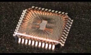
Break Microcontroller TI MSP430F448 can help engineer to disable the protective mechanism of MCU MSP430F448, the firmware in the flash memory can be readout directly with universal programmer
Low Supply-Voltage Range, 1.8 V to 3.6 V
Ultralow-Power Consumption:
– Active Mode: 280 µA at 1 MHz, 2.2 V
– Standby Mode: 1.1 µA
– Off Mode (RAM Retention): 0.1 µA
Five Power Saving Modes
Wake-Up From Standby Mode in 6 µs 16-Bit RISC Architecture,
125-ns Instruction Cycle Time
12-Bit A/D Converter With Internal
Reference, Sample-and-Hold and Autoscan
Feature
16-Bit Timer With Three† or Seven‡
Capture/Compare-With-Shadow Registers, Timer_B Serial Onboard Programming,
No External Programming Voltage Needed Programmable Code Protection by Security Fuse
Integrated LCD Driver for Up to 160 Segments
Family Members Include:
– MSP430F435:
16KB+256B Flash Memory,
512B RAM
– MSP430F436:
24KB+256B Flash Memory,
1KB RAM
– MSP430F437:
32KB+256B Flash Memory,
1KB RAM
16-Bit Timer With Three Capture/Compare Registers, Timer_A On-Chip Comparator Serial Communication Interface (USART), Select Asynchronous UART or Synchronous SPI by Software;
Two USARTs (USART0, USART1) In MSP430x44x Devices One USART (USART0) In MSP430x43x
Devices Brownout Detector Supply Voltage Supervisor/Monitor With Programmable Level Detection
– MSP430F447:
32KB+256B Flash Memory,
1KB RAM
– MSP430F448:
48KB+256B Flash Memory,
2KB RAM
– MSP430F449:
60KB+256B Flash Memory,
2KB RAM
For Complete Module Descriptions, See The MSP430x4xx Family User’s Guide
Literature Number SLAU056 ’F435, ’F436, and ’F437 devices ’F447, ’F448, and ’F449 devices
description
The Texas Instruments MSP430 series is an ultralow-power microcontroller family consisting of several devices featuring different sets of modules targeted to various applications. The microcontroller is designed to be battery operated for use in extended-time applications.
The MSP430 achieves maximum code efficiency with its 16-bit RISC architecture, 16-bit CPU-integrated registers, and a constant generator. The digitally-controlled oscillator provides wake-up from low-power mode to active mode in less than 6 µs.
The MSP430x43x and the MSP430x44x series are microcontroller configurations with two built-in 16-bit timers, a fast 12-bit A/D converter, one or two universal serial synchronous/asynchronous communication interfaces (USART), 48 I/O pins, and a liquid crystal driver (LCD) with up to 160 segments.
![A TI MSP430F448 mikrovezérlő egy alacsony teljesítményű, nagy teljesítményű chip, amelyet általában ipari, orvosi és autóipari alkalmazásokban használnak. Beágyazott flash memória, EEPROM és rögzített firmware -védelemmel rendelkezik az illetéktelen hozzáférés megakadályozása érdekében. Vannak azonban olyan esetek, amikor a felhasználóknak vissza kell állítaniuk, másolni vagy klónozniuk kell a firmware -t - akár biztonsági másolatot, hibakeresést, rendszer migrációját vagy fordított tervezését. A [Az Ön cégneve] oldalán a Mikrovezérlő TI MSP430F448 firmware törésére szakosodunk, segítve az ügyfelek dekódolását, dekódolását és a védett adatok feloldását az elemzéshez és a módosításhoz.](https://www.ic-crack.com/wp-content/uploads/2014/03/1.png)
A TI MSP430F448 mikrovezérlő egy alacsony teljesítményű, nagy teljesítményű chip, amelyet általában ipari, orvosi és autóipari alkalmazásokban használnak. Beágyazott flash memória, EEPROM és rögzített firmware -védelemmel rendelkezik az illetéktelen hozzáférés megakadályozása érdekében. Vannak azonban olyan esetek, amikor a felhasználóknak vissza kell állítaniuk, másolni vagy klónozniuk kell a firmware -t – akár biztonsági másolatot, hibakeresést, rendszer migrációját vagy fordított tervezését. A [Az Ön cégneve] oldalán a Mikrovezérlő TI MSP430F448 firmware törésére szakosodunk, segítve az ügyfelek dekódolását, dekódolását és a védett adatok feloldását az elemzéshez és a módosításhoz.
The TI MSP430F448 microcontroller is a low-power, high-performance chip commonly used in industrial, medical, and automotive applications. It features embedded flash memory, EEPROM, and secured firmware protection to prevent unauthorized access. However, there are cases where users need to restore, copy, or clone the firmware—whether for backup, debugging, system migration, or reverse engineering. At [Your Company Name], we specialize in breaking the microcontroller TI MSP430F448 firmware, helping clients decode, decrypt, and unlock protected data for analysis and modification.
Procedures to Crack TI MSP430F448 Firmware Protection
![Микроконтроллер TI MSP430F448 представляет собой высокопроизводительный чип, обычно используемый в промышленных, медицинских и автомобильных приложениях. Он оснащен встроенной флэш -памятью, EEPROM и защитой прошивки для предотвращения несанкционированного доступа. Тем не менее, есть случаи, когда пользователям необходимо восстановить, копировать или клонировать прошивку - будь то для резервного копирования, отладки, миграции системы или обратной инженерии. В [название вашей компании] мы специализируемся на нарушении прошивки микроконтроллера TI MSP430F448, помогая клиентам декодировать, расшифровать и разблокировать защищенные данные для анализа и модификации.](https://www.ic-crack.com/wp-content/uploads/2014/03/2.png)
Микроконтроллер TI MSP430F448 представляет собой высокопроизводительный чип, обычно используемый в промышленных, медицинских и автомобильных приложениях. Он оснащен встроенной флэш -памятью, EEPROM и защитой прошивки для предотвращения несанкционированного доступа. Тем не менее, есть случаи, когда пользователям необходимо восстановить, копировать или клонировать прошивку – будь то для резервного копирования, отладки, миграции системы или обратной инженерии. В [название вашей компании] мы специализируемся на нарушении прошивки микроконтроллера TI MSP430F448, помогая клиентам декодировать, расшифровать и разблокировать защищенные данные для анализа и модификации.
-
Firmware Extraction – We use advanced hardware tools to read and copy the flash and EEPROM memory, even when the firmware is protected or encrypted. Our techniques allow us to bypass security restrictions and gain access to the heximal or binary data stored in the microcontroller.
-
Disassembly and Reverse Engineering – After extracting the firmware, we decode and disassemble the locked program into machine-readable instructions. This process helps restore the embedded source code and allows deeper analysis of system behavior.
-
Decryption and Source Code Reconstruction – If the firmware is encrypted, we apply specialized algorithms to decrypt and reconstruct the original program. Our goal is to unlock the protected data archive and convert it into a readable and modifiable format.
-
Cloning and Duplication – Once the firmware is extracted and decrypted, we assist in duplicating or cloning the embedded program, making it transferable to other microcontrollers or systems. This step is crucial for system upgrades, debugging, and functional replication.
Why Choose Our TI MSP430F448 Hacking Service?
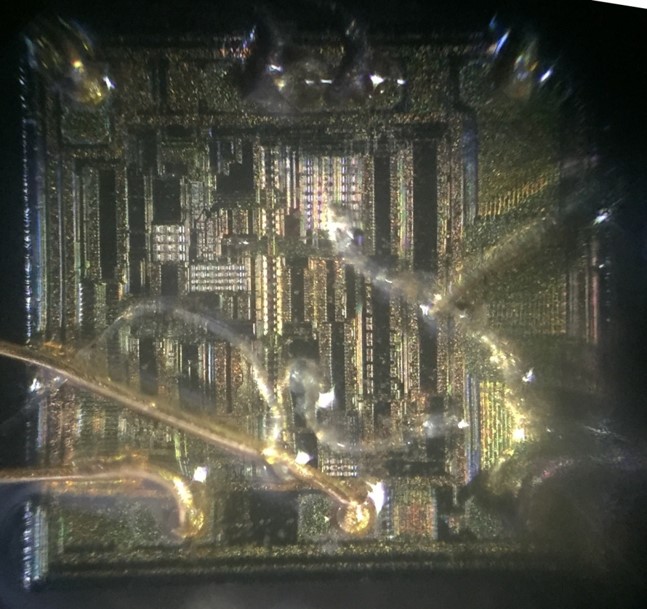
Stručnost u sigurnosnom zaobilaženju Microcontroller – Naš tim ima veliko iskustvo u pucanju zaključanog firmvera i dešifriranju osiguranih memorijskih datoteka.
Napredne tehnike dešifriranja – koristimo najnovije alati za hakiranje firmvera i obrnuti inženjering kako bismo osigurali točno i učinkovito vađenje podataka.
Stroga povjerljivost – Svi projekti upravljaju se s potpunom sigurnošću i povjerljivošću, osiguravajući integritet podataka i privatnost.
-
Expertise in Microcontroller Security Bypass – Our team has extensive experience in cracking locked firmware and decrypting secured memory files.
-
Advanced Decryption Techniques – We use the latest firmware hacking and reverse engineering tools to ensure accurate and efficient data extraction.
-
Strict Confidentiality – All projects are handled with full security and confidentiality, ensuring data integrity and privacy.
If you need to break, unlock, or copy the protected firmware of the TI MSP430F448 microcontroller, contact us today. Our professional reverse engineering solutions will help you restore and duplicate secured software with precision and reliability.
Posted in Break IC |
Tags: break microcontroller binary file, break microcontroller dump information, break microcontroller embedded firmware, break microcontroller encrypt program, break microcontroller flash content, break microcontroller heximal data, break microcontroller locked archive, break microcontroller protect eeprom, break microcontroller software memory, break microcontroller source code |
Comments Closed
Break Microcontroller ATmega164 Code
Break Microcontroller ATmega164 flash memory and extract ATmega164 MCU code from its secured memory, make ATmega164 processor cloning;
With all the features the External Memory Interface provides, it is well suited to operate as an interface to memory devices such as External SRAM and Flash, and peripherals such as LCD-display, A/D, and D/A. The main features are:
Four different wait-state settings (including no wait-state).
Independent wait-state setting for different extErnal Memory sectors (configurable sector size).
The number of bits dedicated to address high byte is selectable.
Bus keepers on data lines to minimize current consumption (optional) if recover mcu atmega2560 flash.
When the eXternal MEMory (XMEM) is enabled, address space outside the internal SRAM becomes available using the dedicated External Memory pins (see Figure 2 on page 3, Table 36 on page 88, Table 42 on page 92, and Table 54 on page 102). The memory configuration is shown in Figure 14.
The interface consists of: AD7:0: Multiplexed low-order address bus and data bus.
A15:8: High-order address bus (configurable number of bits).
ALE: Address latch enable.
RD: Read strobe.
WR: Write strobe.
The control bits for the External Memory Interface are located in two registers, the External Memory Control Register A – XMCRA, and the External Memory Control Register B– XMCRB.
When the XMEM interface is enabled, the XMEM interface will override the setting in the data direction registers that corresponds to the ports dedicated to the XMEM interface.
For details about the port override, see the alternate functions in section “I/O-Ports” on page 81. The XMEM interface will auto-detect whether an access is internal or external if reverse engineering microcontroller atmega1281 program.
If the access is external, the XMEM interface will output address, data, and the control signals on the ports according to Figure 16 (this figure shows the wave forms without wait-states). When ALE goes from high-to-low, there is a valid address on AD7:0. ALE is low during a data transfer.
When the XMEM interface is enabled, also an internal access will cause activity on address, data and ALE ports, but the RD and WR strobes will not toggle during internal access. When the External Memory Interface is disabled, the normal pin and data direction settings are used.
Note that when the XMEM interface is disabled, the address space above the internal SRAM boundary is not mapped into the internal SRAM. Figure 15 illustrates how to connect an external SRAM to the AVR using an octal latch (typically “74 x 573” or equivalent) which is transparent when G is high.
Due to the high-speed operation of the XRAM interface, the address latch must be selected with care for system frequencies above 8 MHz @ 4V and 4 MHz @ 2.7V.
When operating at conditions above these frequencies, the typical old style 74HC series latch becomes inadequate. The External Memory Interface is designed in compliance to the 74AHC series latch. However, most latches can be used as long they comply with the main timing parameters. The main parameters for the address latch are:
D to Q propagation delay (tPD).
Data setup time before G low (tSU).
Data (address) hold time after G low (TH).
The External Memory Interface is designed to guaranty minimum address hold time after G is asserted low of th = 5 ns. Refer to tLAXX_LD/tLLAXX_ST in “External Data Memory Timing” Tables 169 through Tables 176 on pages 376 – 378.
The D-to-Q propagation delay (tPD) must be taken into consideration when calculating the access time requirement of the external component. The data setup time before G low (tSU) must not exceed address valid to ALE low (tAVLLC) minus PCB wiring delay (dependent on the capacitive load).
The pull-ups on the AD7:0 ports may be activated if the corresponding Port register is written to one. To reduce power consumption in sleep mode, it is recommended to disable the pull-ups by writing the Port register to zero before entering sleep.
The XMEM interface also provides a bus-keeper on the AD7:0 lines. The bus-keeper can be disabled and enabled in software as described in “External Memory Control Register B – XMCRB” on page 35. When enabled, the bus-keeper will keep the previous value on the AD7:0 bus while these lines are tri-stated by the XMEM interface.
Posted in Break IC |
Tags: break microcontroller embedded archive, break microcontroller embedded bin, break microcontroller embedded code, break microcontroller embedded content, break microcontroller embedded data, break microcontroller embedded eeprom, break microcontroller embedded file, break microcontroller embedded firmware, break microcontroller embedded hex, break microcontroller embedded information, break microcontroller embedded memory, break microcontroller embedded program |
Comments Closed