 Break Microchip PIC18F2550 MCU Memory
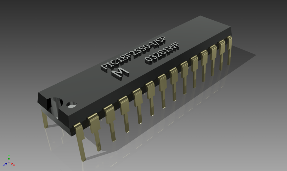
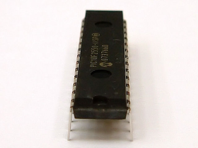
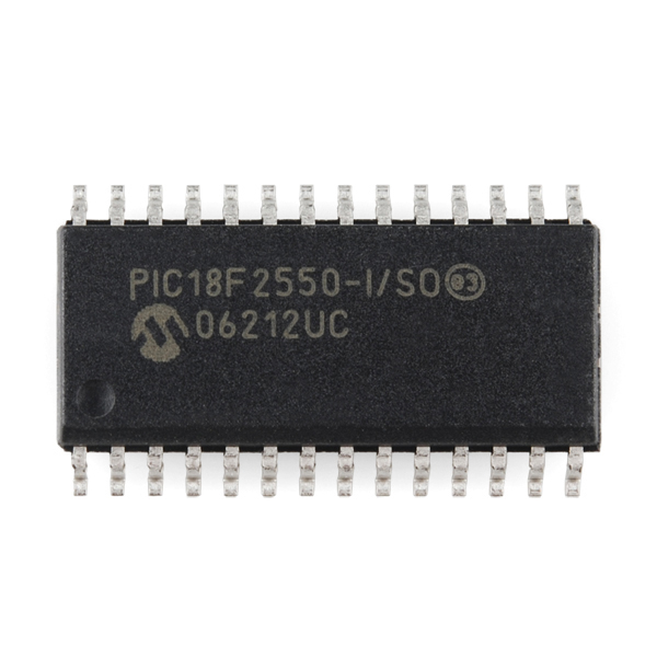
Break Microchip PIC18F2550 MCU memory and restore encrypted microcontroller PIC18F2550’s embedded firmware in the format of binary file or heximal data, through reverse engineering technique to crack down the protective system of locked microprocessor PIC18F2550;
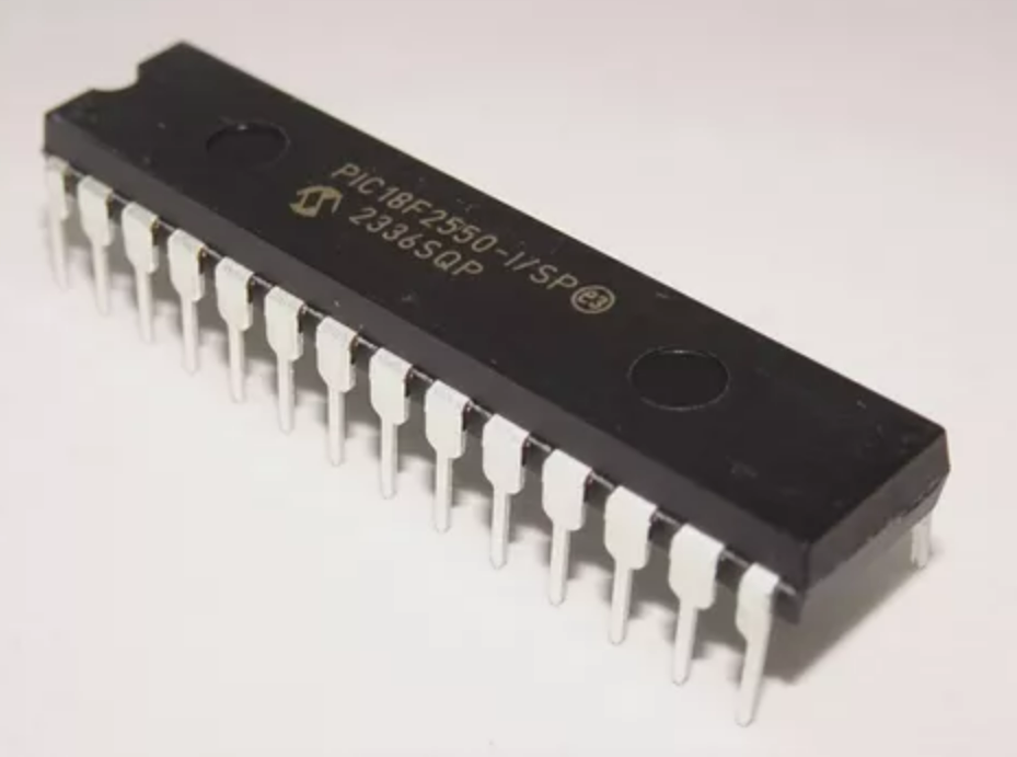
break Microchip PIC18F2550 MCU memory and restore encrypted microcontroller PIC18F2550’s embedded firmware in the format of binary file or heximal data, through reverse engineering technique to crack down the protective system of locked microprocessor PIC18F2550;
PIC18F2550 devices offer a total of seven operating modes for more efficient power management by Crack MCU Firmware. These modes provide a variety of options for selective power conservation in applications where resources may be limited and Break Microchip PIC18F2550 MCU Memory (i.e., battery-powered devices).
There are three categories of power-managed modes:
• Run modes
• Idle modes
• Sleep mode
These categories define which portions of the device are clocked and sometimes, what speed. The Run and Idle modes may use any of the three available clock sources when Attack Microchip PIC18F2525 Processor Memory (primary, secondary or internal oscillator block). The Sleep mode does not use a clock source.
The power-managed modes include several power- saving features offered on previous PIC® devices.
Kilitli mikroişlemci PIC18F2550’nin koruyucu sistemini çökertmek için tersine mühendislik tekniği kullanarak Microchip PIC18F2550 MCU belleğini kırın ve şifrelenmiş mikrodenetleyici PIC18F2550’nin gömülü aygıt yazılımını ikili dosya veya onaltılık veri biçiminde geri yükleyin;
One is the clock switching feature, offered in other PIC18 devices, allowing the controller to use the Timer1 oscillator in place of the primary oscillator to facilitate the process of Reverse Engineering PIC18F2520 Controller. Also included is the Sleep mode, offered by all PIC devices, where all device clocks are stopped.
Break Microchip PIC18F2550 MCU Memory
Selecting a power-managed mode requires two decisions: if the CPU is to be clocked or not and the selection of a clock source. The IDLEN bit (OSCCON<7>) controls CPU clocking, while the SCS1:SCS0 bits (OSCCON<1:0>) select the clock source for the purpose of Break PIC18F2523 CPU Memory. The individual modes, bit settings, clock sources and affected modules are summarized in below Table.
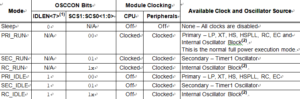
The SCS1:SCS0 bits allow the selection of one of three clock sources for power-managed modes.
sparge memoria Microchip PIC18F2550 MCU și restaura firmware-ul încorporat al microcontrolerului criptat PIC18F2550 în format de fișier binar sau date heximale, prin tehnica de inginerie inversă pentru a distruge sistemul de protecție al microprocesorului blocat PIC18F2550;
They are: the primary clock, as defined by the FOSC3:FOSC0 Configuration bits to Microprocessor PIC18F2515 Heximal File Recovery
the secondary clock (the Timer1 oscillator)
the internal oscillator block (for RC modes)
briser la mémoire du microcontrôleur Microchip PIC18F2550 et restaurer le micrologiciel intégré crypté du microcontrôleur PIC18F2550 au format de fichier binaire ou de données hexadécimales, grâce à une technique d’ingénierie inverse pour déchiffrer le système de protection du microprocesseur verrouillé PIC18F2550 ;