Archive for the ‘Break IC’ Category
 Break IC PIC12F635 Program
 October 9th, 2014 |
  Author:
 Break IC PIC12F635 Program
Break IC PIC12F635 Program from eeprom and flash memory, and extract it out from it:
High-Performance RISC CPU:
· Only 35 instructions to learn:
– All single-cycle instructions except branches
· Operating speed:
– DC – 20 MHz oscillator/clock input
– DC – 200 ns instruction cycle
· Interrupt capability
· 8-level deep hardware stack
· Direct, Indirect and Relative Addressing modes
Special Microcontroller Features:
· Precision Internal Oscillator:
– Factory calibrated to ±1%
– Software selectable frequency range of 8 MHz to 31 kHz
– Software tunable
– Two-Speed Start-up mode
– Crystal fail detect for critical applications
· Clock mode switching for low power operation
· Power-saving Sleep mode
· Wide operating voltage range (2.0V-5.5V)
· Industrial and Extended Temperature range
· Power-on Reset (POR)
· Wake-up Reset (WUR)
· Independent weak pull-up/pull-down resistors
· Programmable Low-Voltage Detect (PLVD)
· Power-up Timer (PWRT) and Oscillator Start-up Timer (OST)
· Brown-out Detect (BOD) with software control option
· Enhanced Low-Current Watchdog Timer (WDT) with on-chip oscillator (software selectable nominal 268 seconds with full prescaler) with software enable
· Multiplexed Master Clear with pull-up/input pin
· Programmable code protection (program and data independent)
· High-Endurance Flash/EEPROM cell:
– 100,000 write Flash endurance
– 1,000,000 write EEPROM endurance
– Flash/Data EEPROM Retention: > 40 years
· Standby Current:
– 1 nA @ 2.0V, typical
· Operating Current:
– 8.5 ìA @ 32 kHz, 2.0V, typical
– 100 ìA @ 1 MHz, 2.0V, typical
– 1 ìA @ 2.0V, typical
 Posted in
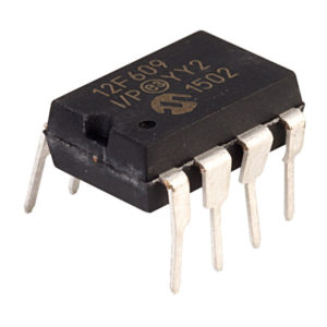
Break IC PIC12F609 Heximal
Break IC PIC12F609 Heximal
Break IC PIC12F609 Heximal from eeprom and flash memory, and then transfer the heximal into other blank PIC12F609 which will provide the same functions:
Program Memory Organization
The PIC12F609 has a 13-bit program counter capable of addressing an 8K x 14 program memory space. Only the first 1K x 14 (0000h-03FFh) for the PIC12F609/615/12HV609/615 is physically implemented. Accessing a location above these boundaries will cause a wraparound within the first 1K x 14 space. The Reset vector is at 0000h and the interrupt vector is at 0004h.
Data Memory Organization
The data memory (see Figure 2-2) is partitioned into two banks, which contain the General Purpose Registers (GPR) and the Special Function Registers (SFR). The Special Function Registers are located in the first 32 locations of each bank.
Register locations 40h-7Fh in Bank 0 are General Purpose Registers, implemented as static RAM. Register locations F0h-FFh in Bank 1 point to addresses 70h-7Fh in Bank 0. All other RAM is unimplemented and returns ‘0’ when read. The RP0 bit of the STATUS register is the bank select bit.
Break IC PIC12F609 Heximal
The Special Function Registers are registers used by the CPU and peripheral functions for controlling the desired operation of the device. These registers are static RAM.
The special registers can be classified into two sets: core and peripheral. The Special Function Registers associated with the “core” are described in this section. Those related to the operation of the peripheral features are described in the section of that peripheral feature.
The STATUS register, shown in Register 2-1, contains:
· the arithmetic status of the ALU
· the Reset status
· the bank select bits for data memory (RAM)
The STATUS register can be the destination for any instruction, like any other register. If the STATUS register is the destination for an instruction that affects the Z, DC or C bits, then the write to these three bits is disabled. These bits are set or cleared according to the device logic. Furthermore, the TO and PD bits are not writable. Therefore, the result of an instruction with the STATUS register as destination may be different than intended for the purpose of CLONE IC.
Break IC PIC12F615 Software
Break IC PIC12F615 Software
Break IC PIC12F615 Software from its memory, it is important to know the basic features of PIC12F615 and then disable its protection mechanism:
High-Performance RISC CPU:
· Only 35 instructions to learn:
– All single-cycle instructions except branches
· Operating speed:
– DC – 20 MHz oscillator/clock input
– DC – 200 ns instruction cycle
· Interrupt capability
· 8-level deep hardware stack
· Direct, Indirect and Relative Addressing modes
Special Microcontroller Features:
· Precision Internal Oscillator:
– Factory calibrated to ±1%, typical
– Software selectable frequency: 4 MHz or 8 MHz
· Power-Saving Sleep mode
· Voltage range:
– PIC12F609/615: 2.0V to 5.5V
– PIC12HV609/615: 2.0V to user defined maximum (see note)
· Industrial and Extended Temperature range
· Power-on Reset (POR)
· Power-up Timer (PWRT) and Oscillator Start-up Timer (OST)
· Brown-out Reset (BOR)
· Watchdog Timer (WDT) with independent oscillator for reliable operation
· Multiplexed Master Clear with pull-up/input pin
· Programmable code protection
· High Endurance Flash:
– 100,000 write Flash endurance
– Flash retention: > 40 years
Break IC PIC12F615 Software
Low-Power Features:
· Standby Current:
– 50 nA @ 2.0V, typical
· Operating Current:
– 11 ìA @ 32 kHz, 2.0V, typical
– 260 ìA @ 4 MHz, 2.0V, typical
· Watchdog Timer Current:
– 1 ìA @ 2.0V, typical
Peripheral Features:
· Shunt Voltage Regulator (PIC12HV609/615 only)
– 5 volt regulation
– 4 mA to 50 mA shunt range
· 5 I/O pins and 1 input only
· High current source/sink for direct LED drive
– Interrupt-on-pin change or pins
– Individually programmable weak pull-ups
· Analog Comparator module with:
– One analog comparator
– Programmable on-chip voltage reference (CVREF) module (% of VDD)
– Comparator inputs and output externally accessible
– Built-In Hysteresis (software selectable)
· Timer0: 8-bit timer/counter with 8-bit programmable prescaler
· Enhanced Timer1:
– 16-bit timer/counter with prescaler
– External Timer1 Gate (count enable)
– Option to use OSC1 and OSC2 in LP mode as Timer1 oscillator if INTOSC mode selected
– Option to use system clock as Timer1
· In-Circuit Serial ProgrammingTM (ICSPTM) via two pins
PIC12F615/HV615 ONLY:
· Enhanced Capture, Compare, PWM module:
– 16-bit Capture, max. resolution 12.5 ns
– Compare, max. resolution 200 ns
– 10-bit PWM with 1 or 2 output channels, 1 output channel programmable “dead time”, max. frequency 20 kHz, auto-shutdown
· A/D Converter:
– 10-bit resolution and 4 channels, samples internal voltage references
· Timer2: 8-bit timer/counter with 8-bit period register, prescaler and postscaler
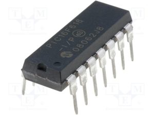
Break IC PIC16F616 Heximal
Break IC PIC16F616 Heximal
Break IC PIC16F616 Heximal from the program memory, below we will introduce the program memory organization chart so you can have a better idea about how to get access to the wafer die:
PIC16F616/16HV616 only:
· A/D Converter:
– 10-bit resolution
– 8 external input channels
– 2 internal reference channels
· Timer2: 8-bit timer/counter with 8-bit period register, prescaler and postscaler
· Enhanced Capture, Compare, PWM module:
– 16-bit Capture, max. resolution 12.5 ns
– 16-bit Compare, max. resolution 200 ns
– 10-bit PWM with 1, 2 or 4 output channels, programmable “dead time”, max. frequency 20 kHz
Program Memory Organization of PIC16F616/16HV616
The PIC16F610/616/16HV610/616 has a 13-bit program counter capable of addressing an 8k x 14 program memory space. Only the first 1K x 14 (0000h-3FF) for the PIC16F610/16HV610 and the first 2K x 14 (0000h-07FFh) for the PIC16F616/16HV616 is physically implemented. Accessing a location above these boundaries will cause a wraparound within the first 1K x 14 space (PIC16F610/16HV610) and 2K x 14 space (PIC16F616/16HV616). The Reset vector is at 0000h and the interrupt vector is at 0004h.
Break IC PIC16F616 Heximal
The data memory (see Figure 2-4) is partitioned into two banks, which contain the General Purpose Registers (GPR) and the Special Function Registers (SFR). The Special Function Registers are located in the first 32 locations of each bank.
PIC16F610/16HV610 Register locations 40h-7Fh in Bank 0 are General Purpose Registers, implemented PC gram counter capable of addressing an 8k x 14 program memory space. Only the first 1K x 14 (0000h-3FF) for the PIC16F610/16HV610 and the first 2K x 14 (0000h-07FFh) for the PIC16F616/16HV616 is physically implemented.
Accessing a location above these boundaries will cause a wraparound within the first 1K x 14 space (PIC16F610/16HV610) and 2K x 14 space (PIC16F616/16HV616). The Reset vector is at 0000h and the interrupt vector is at 0004h.
Break IC PIC16F88 Data
Break IC PIC16F88 Data
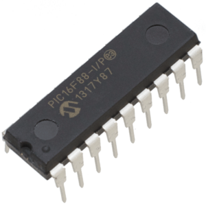
This document contains device specific information for the operation of Break IC PIC16F88 Data. Additional information may be found in the PICmicro® Mid-Range MCU Reference Manual (DS33023) which may be downloaded from the Microchip website.
This Reference Manual should be considered a complementary document to this data sheet, and is highly recommended breaking for a better understanding of the device architecture and operation of the peripheral modules.
The PIC16F88 belongs to the Mid-Range family of the PICmicro® devices. Block diagrams of the devices are shown in Figure 1-1 and Figure 1-2. These devices contain features that are new to the PIC16 product line:
· Low-power modes: RC_RUN allows the core and peripherals to be clocked from the INTRC, while SEC_RUN allows the core and peripherals to be clocked from the low-power Timer1.
Break IC PIC16F88 Data
· Internal RC oscillator with eight selectable frequencies, including 31.25 kHz, 125 kHz, 250 kHz, 500 kHz, 1 MHz, 2 MHz, 4 MHz, and 8 MHz. The INTRC can be configured as a primary or secondary clock source.
· The Timer1 module current consumption has been greatly reduced from 20 µA (previous PIC16 devices) to 1.8 µA typical (32 kHz at 2V), which is ideal for real-time clock applications.
· Extended Watchdog Timer (WDT) that can have a programmable period from 1 ms to 268s. The WDT has its own 16-bit prescaler.
· Two-Speed Start-up: When the oscillator is configured for LP, XT, or HS, this feature will clock the device from the INTRC while the oscillator is warming up. This, in turn, will enable almost immediate code execution.
· The A/D module has a new register for PIC16 devices named ANSEL. This register allows easier configuration of analog or digital I/O pins.
Break IC PIC16F715 Firmware
We can Break IC PIC16F715 Firmware, please view the IC PIC16F715 features for your reference:
PIC16C71X devices are supported by the complete line of Microchip Development tools. Please refer to Section 10.0 for more details about Microchip’s development tools.
A variety of frequency ranges and packaging options are available. Depending on application and production requirements, the proper device option can be selected using the information in the PIC16C71X Product Identification System section at the end of this data sheet.
When placing orders, please use that page of the data sheet to specify the correct part number.
For the PIC16C71X family, there are two device “types” as indicated in the device number:
1. C, as in PIC16C71. These devices have EPROM type memory and operate over the standard voltage range.
2. LC, as in PIC16LC71. These devices have EPROM type memory and operate over an extended voltage range.
The UV erasable version, offered in CERDIP package is optimal for prototype development and pilot programs.
Break IC PIC16F715 Firmware
This version can be erased and reprogrammed to any of the oscillator modes.
Microchip’s PICSTART® Plus and PRO MATE® II programmers both support programming of the PIC16C71X.
One-Time-Programmable (OTP) Devices
The OTP devices, packaged in plastic packages, permit the user to program them once. In addition to the program memory, the configuration bits must also be programmed.
Microchip offers a QTP Programming Service for factory production orders. This service is made available for users who choose not to program a medium to high quantity of units and whose code patterns have stabilized.
The devices are identical to the OTP devices but with all EPROM locations and configuration options already programmed by the factory. Certain code and prototype verification procedures apply before production shipments are available. Please contact your local Microchip Technology sales office for more details.
Attack IC PIC16F57 Program
The Microchip PIC16F57 is a robust 8-bit microcontroller widely used in consumer electronics, industrial controllers, automotive modules, and various embedded systems. With its compact architecture, onboard I/O, and reliable performance, it is a preferred solution in many secured or proprietary control units. However, the firmware, binary, or heximal files stored within these chips are often protected or encrypted, making them inaccessible without expert intervention.
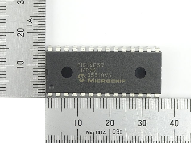
At Circuit Engineering Co., LTD, we provide professional services to attack IC PIC16F57 program protection mechanisms, enabling clients to recover, copy, or restore the original program data. Whether the chip is locked, secured, or obfuscated, our team is equipped with the latest tools and methodologies to crack and decrypt the internal memory, including flash and EEPROM sections.
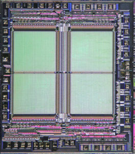
The PIC16F5X from Microchip Technology is a family of low-cost, high-performance, 8-bit, fully static, Flash based CMOS microcontrollers. It employs a RISC architecture with only 33 single-word/single-cycle instructions. All instructions are single cycle except for program branches which take two cycles by Attack IC PIC16F57 Program. The PIC16F5X delivers performance an order of magnitude higher than its competitors in the same price category.
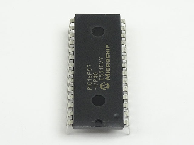
The 12-bit wide instructions are highly symmetrical resulting in 2:1 code compression over other 8-bit microcontrollers in its class. The easy-to-use and easy-to-remember instruction set reduces development time significantly.
The PIC16F5X products are equipped with special features that reduce system cost and power requirements. The Power-on Reset (POR) and Device Reset Timer (DRT) eliminate the need for external Reset circuitry.
There are four oscillator configurations to choose from, including the power-saving LP (Low Power) oscillator and cost saving RC oscillator. Power-saving Sleep mode, Watchdog Timer and code protection features improve system cost, power and reliability.
The PIC16F57 is a baseline 12-bit core MCU with a 2K x 12-word flash program memory, 72 bytes of RAM, and 16 I/O pins. It is notable for its simplicity and low cost, making it ideal for mass-produced applications like remote controllers, basic logic units, small motors, timers, and more. In legacy systems where documentation has been lost or when a supplier no longer provides source support, reverse engineering becomes the only solution to continue development or maintenance.
Our service is especially valuable to:
- OEMs needing to duplicate legacy designs.
- Engineers aiming to clone or migrate control logic to a modern platform.
- Security analysts looking to decode encrypted systems for vulnerability assessments.
- Researchers interested in system behavior analysis or functional replication.
The PIC16F5X products are supported by a full-featured macro assembler, a software simulator, a low-cost development programmer and a full featured programmer. All the tools are supported on IBM® PC and compatible machines.
We begin with physical or electrical-level attacks to bypass code protection bits embedded in the PIC16F57. Once access is achieved, we dump the program file—usually in heximal format—from the internal memory. After extraction, we optionally provide detailed analysis, disassembly, and conversion to assembly or even C-style source code, depending on the client’s needs.
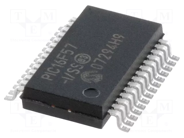
Whether your chip is locked, masked, or fused, we have experience dealing with a wide range of protected microcontrollers and can offer customized recovery or cloning solutions.
The PIC16F5X series fits perfectly in applications ranging from high-speed automotive and appliance motor control to low-power remote transmitters/receivers, pointing devices and telecom processors. The Flash technology makes customizing application programs from Attack IC PIC16F57 Program (transmitter codes, motor speeds, receiver frequencies, etc.) extremely fast and convenient.
The small footprint packages, for through hole or surface mounting, make this microcontroller series perfect for applications with space limitations. Low-cost, low-power, high performance, ease of use and I/O flexibility make the PIC16F5X series very versatile, even in areas where no microcontroller use has been considered before (e.g., timer functions, replacement of “glue” logic in larger systems, co-processor applications).
It’s important to understand that our service is tailored for legitimate recovery, engineering evaluation, or system restoration purposes. Clients rely on us not only for our technical proficiency but also for our professional handling of confidential projects. All engagements are strictly private and aligned with legal and ethical standards.
If you’re facing a development halt due to inaccessible code within a PIC16F57, or if you’re looking to unlock archived data or restore a functional system from a non-functional unit, we’re here to help. With our “Attack IC PIC16F57 Program” service, we help you regain control of your systems by retrieving the irreplaceable firmware buried deep inside secured embedded chips.
Let us help you bring the hidden logic back to light. Contact us today to discuss your project in confidence.
Break IC PIC16F648A Heximal
FLASH devices can be erased and re-programmed electrically which is a critical feature when Break IC PIC16F648A Heximal. This allows the same device to be used for prototype development, pilot programs and production.
A further advantage of the electrically erasable FLASH is that it can be erased and reprogrammed in-circuit, or by device programmers, such as Microchip’s PICSTART® Plus, or PRO MATE® II programmers.
The high performance of the PIC16F648A family can be attributed to a number of architectural features commonly found in RISC microprocessors. To begin with, the PIC16F648A uses a Harvard architecture, in which program and data are accessed from separate memories using separate busses.
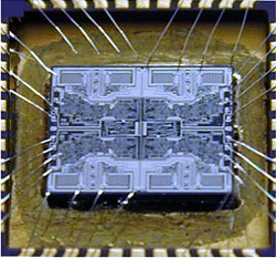
Break IC PIC16F648A Heximal
This improves bandwidth over traditional von Neumann architecture where program and data are fetched from the same memory when Break IC PIC16F648A Heximal. Separating program and data memory further allows instructions to be sized differently than 8-bit wide data word. Instruction opcodes are 14-bits wide making it possible to have all single word instructions.
A 14-bit wide program memory access bus fetches a 14-bit instruction in a single cycle. A two-stage pipeline overlaps fetch and execution of instructions. Consequently, all instructions (35) execute in a single-cycle (200 ns @ 20 MHz) except for program branches.
(QTP) Devices Microchip offers a QTP Programming Service for factory production orders. This service is made available for users who chose not to program a medium to high quantity of units and whose code patterns have stabilized.
The devices are standard FLASH devices but with all program locations and configuration options already programmed by the factory. Certain code and prototype verification procedures apply before production shipments are available.
Microchip offers a unique programming service where a few user-defined locations in each device are programmed with different serial numbers. The serial numbers may be random, pseudo-random or sequential. Serial programming allows each device to have a unique number, which can serve as an entry-code, password or ID number.
Break Microcontroller PIC16F690 Heximal
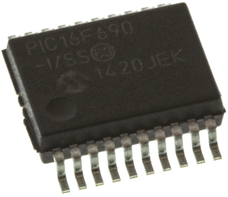
The PIC16F690 stands out as a highly versatile member of the 8-bit embedded family, prized for its integrated peripherals and low power consumption. This microcontroller is a staple in diverse sectors, including smart home automation, portable medical instruments, and automotive lighting systems. Its unique architecture combines a high-speed flash memory with an integrated eeprom for non-volatile data storage, providing a robust platform for complex program logic. In many industrial applications, this chip serves as the central hub for processing sensor data or managing communication protocols. However, because these units are often shipped with locked or protected security bits to prevent unauthorized access, maintaining or upgrading older systems becomes a significant challenge when the original source code is no longer available.
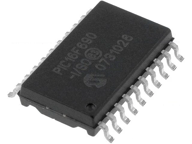
Our specialized lab services offer a reliable methodology to break these hardware barriers and retrieve the essential heximal data required for system continuity. To successfully attack a secured device, our technicians may decapsulate the physical package to gain direct access to the internal silicon circuitry. By bypassing the protective security fuses, we can effectively decode the binary archive stored within the flash and eeprom layers. Whether your goal is to clone a legacy PLD or duplicate the firmware from a failing board, our process ensures a high-fidelity extraction of the embedded file. This professional approach allows companies to hack through the limitations of obsolete hardware, ensuring that critical program instructions are recovered and preserved for future use.
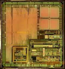
We can Break Microcontroller PIC16F690 Heximal, please view the Microcontroller PIC16F684 features for your reference:
High-Performance RISC CPU:
· Only 35 instructions to learn:
– All single-cycle instructions except branches
· Operating speed:
– DC – 20 MHz oscillator/clock input
– DC – 200 ns instruction cycle
· Interrupt capability
· 8-level deep hardware stack
Low-Power Features:
· Standby Current:
– 1 nA @ 2.0V, typical
· Operating Current:
– 8.5 µA @ 32 kHz, 2.0V, typical
– 100 µA @ 1 MHz, 2.0V, typical
· Watchdog Timer Current:
– 1 µA @ 2.0V, typical
· Direct, Indirect and Relative Addressing modes
Peripheral Features:
Special Microcontroller Features:
· Precision Internal Oscillator:
– Factory calibrated to ±1%
– Software selectable frequency range of 8 MHz to 31 kHz
– Software tunable
– Two-speed Start-up mode
– Crystal fail detect for critical applications
– Clock mode switching during operation for power savings
· Power-saving Sleep mode
· Wide operating voltage range (2.0V-5.5V)
· Industrial and Extended Temperature range
· Power-on Reset (POR)
· Power-up Timer (PWRT) and Oscillator Start-up Timer (OST)
· Brown-out Detect (BOD) with software control option
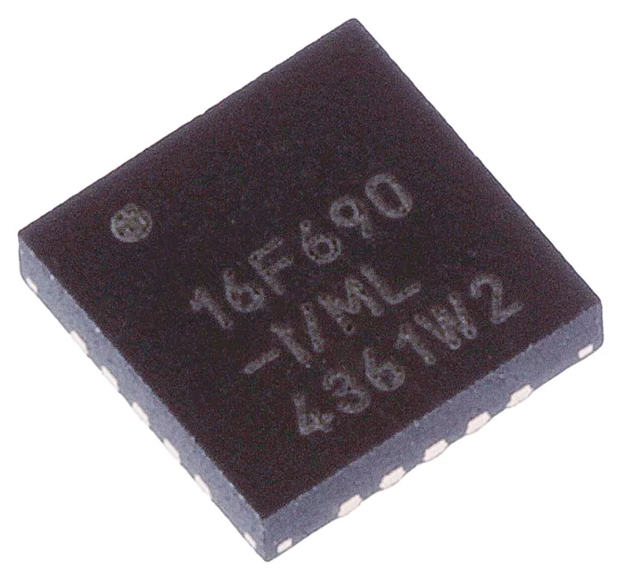
· Enhanced low-current Watchdog Timer (WDT) with on-chip oscillator (software selectable nominal 268 seconds with full prescaler) with software enable to facilitate the process of Break Microcontroller PIC16F690 Heximal.
· Multiplexed Master Clear with pull-up/input pin
· Programmable code protection
· High Endurance Flash/EEPROM cell:
– 100,000 write Flash endurance
– 1,000,000 write EEPROM endurance
– Flash/Data EEPROM retention: > 40 years
· 12 I/O pins with individual direction control:
– High current source/sink for direct LED drive
– Individually programmable weak pull-ups
– Ultra Low-power Wake-up (ULPWU)
· Analog comparator module with:
– Two analog comparators
– Programmable on-chip voltage reference (CVREF) module (% of VDD)
– Comparator inputs and outputs externally accessible
· A/D Converter:
– 10-bit resolution and 8 channels
· Timer0: 8-bit timer/counter with 8-bit programmable prescaler
· Enhanced Timer1:
– 16-bit timer/counter with prescaler
– External Gate Input mode
– Option to use OSC1 and OSC2 in LP mode as Timer1 oscillator if INTOSC mode selected
· Timer2: 8-bit timer/counter with 8-bit period register, prescaler and postscaler
· Enhanced Capture, Compare, PWM module:
– 16-bit Capture, max resolution 12.5 ns
– Compare, max resolution 200 ns
– 10-bit PWM with 1, 2 or 4 output channels, programmable “dead time”, max frequency 20 kHz
· In-Circuit Serial ProgrammingTM (ICSPTM) via two pins
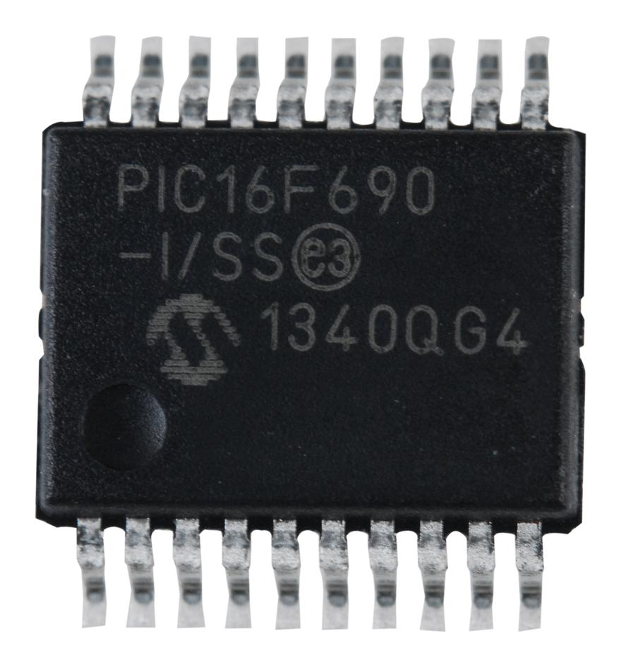
The primary motivation to break a protected PIC16F690 is often to ensure long-term equipment reliability and to mitigate the risks of component end-of-life. By choosing to decode or attack the locked security of a microcontroller, an engineer can retrieve the heximal file needed to clone or duplicate a vital system component. This is particularly beneficial for the end user who needs to hack the software limitations of a secured device to perform repairs or essential firmware updates. Our service transforms a protected binary archive back into a usable source code equivalent, allowing you to duplicate the flash content and transfer it to new hardware. This prevents the total loss of proprietary logic and ensures that your embedded memory remains an asset rather than a liability.
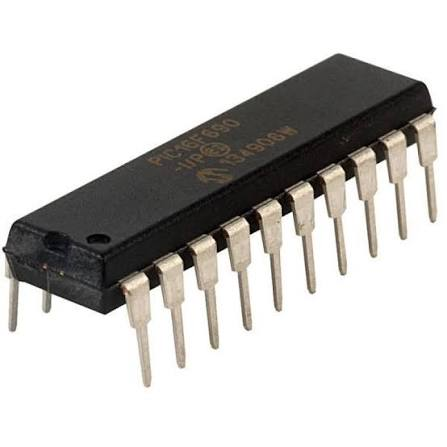
Choosing our service provides immediate benefits by reducing the downtime associated with manual software redevelopment. Instead of starting from scratch, you can retrieve the heximal program and clone the locked data directly onto a fresh chip. Our expertise in how to decapsulate and attack these high-security microcontrollers ensures that the encrypted or protected logic is handled with surgical precision. We help you break the cycle of forced obsolescence by providing a path to decode and duplicate the firmware of any secured PIC16F690. Ultimately, we provide the technical bridge between a protected binary file and a fully functional, restored system, ensuring your eeprom and flash data are always within reach.
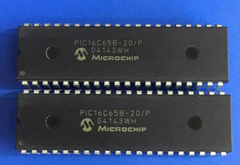
Break Microcontroller PIC16C65B Eeprom
The PIC16C65B microcontroller is a cornerstone of the 8-bit embedded world, renowned for its high-performance RISC architecture and versatile I/O capabilities. In various industries—ranging from automotive engine control units and industrial automation sensors to medical monitoring devices and consumer electronics—this chip serves as the brain for sophisticated logic. Its unique features, such as a wide operating voltage and an embedded architecture that integrates flash, eeprom, and high-speed memory, make it an ideal choice for developers seeking reliability. However, when legacy systems face hardware failure or when documentation is lost, the secured nature of the protected logic within the locked program area can present a significant hurdle for maintenance and reverse engineering.
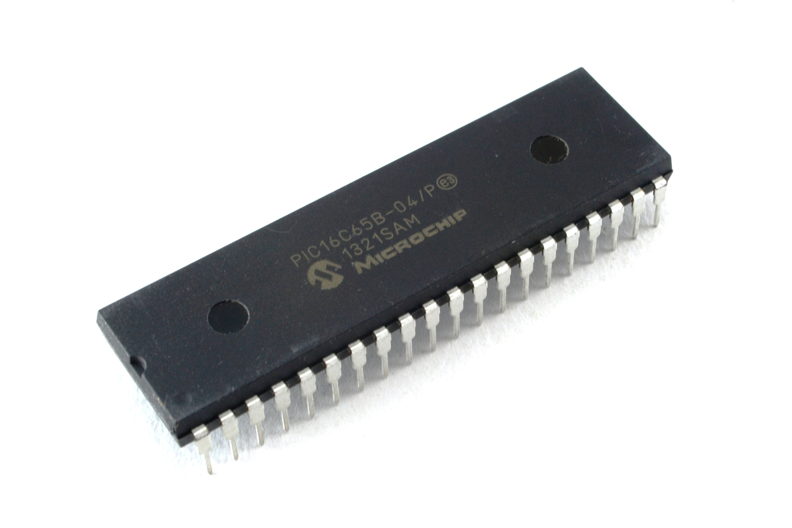
Our specialized service provides a professional pathway to break through these barriers and retrieve the critical source code or heximal data stored within these devices. By utilizing advanced lab techniques to decapsulate the physical package, we can directly access the silicon die to decode and attack the protective security bits that prevent standard reading. Whether you need to clone a discontinued component for system repair or duplicate the firmware from a secured PLD to ensure long-term stability, our process carefully extracts the binary archive without damaging the underlying logic. This allows manufacturers to hack the limitations of obsolete hardware, ensuring that a vital file or program is not lost to time, ultimately providing a cost-effective alternative to complete system redesigns.
The PIC16CXX microcontroller family has enhanced core features, eight-level deep stack and multiple internal and external interrupt sources.
The separate instruction and data buses of the Harvard architecture allow a 14-bit wide instruction word with the separate 8-bit wide data. The two stage instruction pipeline allows all instructions to execute in a single cycle, except for program branches, which require two cycles, A total of 35 instructions (reduced instruction set) are available. Additionally, a large register set gives some of the architectural innovations used to achieve a very high performance.
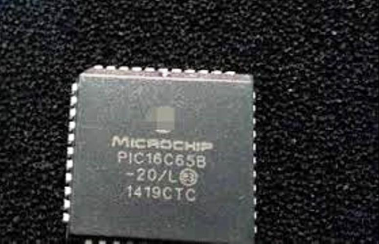
The PIC16C63A/73B devices have 22 I/O pins. The PIC16C65B/74B devices have 33 I/O pins. Each device has 192 bytes of RAM. In addition, several peripheral features are available, including: three timer/ counters, two Capture/Compare/PWM modules, and two serial ports;
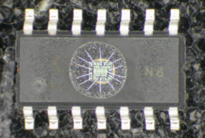
The Synchronous Serial Port (SSP) can be configured as either a 3-wire Serial Peripheral Interface (SPI) or the two-wire Inter-Integrated Circuit (I 2C) bus. The Universal Synchronous Asynchronous Receiver Transmitter (USART) is also known as the Serial Communications Interface or SCI. Also, a 5- channel high speed 8-bit A/D is provided while the PIC16C74B offers 8 channels.
The 8-bit resolution is ideally suited for applications requiring low cost analog interface, e.g., thermostat control, pressure sensing, etc. The PIC16C65B devices have special features to reduce external components, thus reducing cost, enhancing system reliability and reducing power consumption which makes engineer more likely to choose it as the next generation of device and necessary to Break Microcontroller PIC16C65B Eeprom.
There are four oscillator options, of which the single pin RC oscillator provides a low cost solution, the LP oscillator minimizes power consumption, XT is a standard crystal, and the HS is for high speed crystals. The SLEEP (power-down) feature provides a power-saving mode. The user can wake-up the chip from SLEEP through several external and internal interrupts and RESETS.
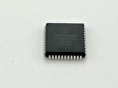
The primary purpose of such an attack on a locked eeprom is rarely about compromise, but rather about continuity and recovery. For many end users, the ability to duplicate the flash content from a protected unit means they can keep multi-million dollar production lines running when the original supplier no longer exists. By choosing to decode or hack the embedded security of a PIC16C65B, you gain the ability to retrieve the heximal archive needed to clone failing hardware, effectively turning a secured “black box” back into a manageable source code asset. Our technical expertise in how to decapsulate and break these chips ensures that the binary data is extracted with 100% integrity, allowing for a seamless duplicate of the firmware onto a new memory chip.
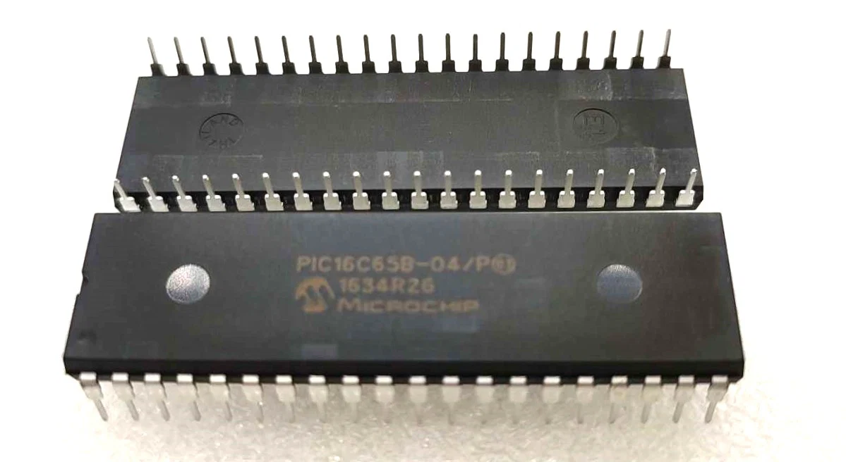
For the end user, the benefits of our firmware extraction service are both financial and operational. Instead of facing the daunting task of rewriting complex software from scratch, you can retrieve the existing heximal file and clone the locked program to a fresh microcontroller. This ensures that the encrypted or protected intellectual property remains functional within your specific application, whether that is a high-precision data logger or a secured industrial controller. We provide the tools to decode and break the limitations of embedded silicon, turning a protected archive into a usable binary again. By choosing our service to decapsulate and attack these hardware locks, you ensure that your flash and eeprom data remains accessible, reliable, and ready for the next generation of your technology.