Texas Instrument DSP TMS320F28069FPNT MCU Binary Restoration
Texas Instrument DSP TMS320F28069FPNT MCU Binary Restoration can be executed through cracking dsp locked microcontroller tms320f28069 fuse bit, then readout flash memory program from processor tms320f28069;
Based on the end application design and operational profile, the IDD and IDDIO currents could vary. Systems that exceed the recommended maximum power dissipation in the end product may require additional thermal enhancements. Ambient temperature (TA) varies with the end application and product design. The critical factor that affects reliability and functionality is TJ, the junction temperature, not the ambient temperature.
Hence, care should be taken to keep TJ within the specified limits. Tcase should be measured to estimate the operating junction temperature TJ. Tcase is normally measured at the center of the package top-side surface when breaking ti mcu tms320f28034png. The thermal application report Semiconductor and IC Package Thermal Metrics helps to understand the thermal metrics and definitions.
Восстановление двоичного кода микроконтроллера Texas Instrument DSP TMS320F28069FPNT может быть выполнено путем взлома заблокированного микроконтроллера tms320f28069 фьюз-бита dsp, а затем считывания программы флэш-памяти из процессора tms320f28069.
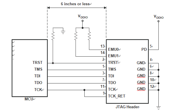
Below Figure shows the connection between the MCU and JTAG header for a single-processor configuration. If the distance between the JTAG header and the MCU is greater than 6 inches, the emulation signals must be buffered. If the distance is less than 6 inches to attack tms320f28235pg microprocessor protection system, buffering is typically not needed. Below Figure shows the simpler, no-buffering situation. For the pullup/pulldown resistor values, see Section 6.2, Signal Descriptions.