Posts Tagged ‘recover mcu embedded memory’
 ATmega861A: Telling Library Code From Yours in Eight Kilobytes
 November 9th, 2010 |
 Author:
Every compiled image contains two kinds of code: what the developer wrote and what the toolchain supplied. At eight kilobytes both are present in quantity, and the ability to tell them apart is what makes an analysis tractable — because one half can be skimmed and the other cannot.
The boundary is not marked. It has to be inferred, and there are reliable signals.
Signals that identify library code
Repetitive structure. Multiplication, division, and long-integer arithmetic compile into tight loops with a characteristic shape. Two such loops in an image usually mean the same routine was emitted twice, or that one is multiply and one is divide.
No peripheral access. Library routines touch memory, not registers. A function whose body contains no write to a hardware register address is almost certainly compiler-generated.
Called from many places, calls nothing. A leaf function with many callers and no callees is either a utility or a hardware abstraction the developer wrote. Its body distinguishes the two.
Fixed, recognisable prologues. Saving and restoring registers around a computation produces a repeated pattern at entry and exit, which is a strong hint that the body was generated rather than written.
Signals that identify application code
The complement is easier to spot:
- Writes to peripheral registers with addresses in the hardware range.
- Reads of status flags followed by conditional branches.
- Delay loops sized with round numbers.
- Table lookups whose index comes from an analogue reading.
That last item is where the product usually is. A table indexed by an ADC result means a calibration curve, a display segment map, or a threshold set — and all three are design decisions rather than mechanical translation.
| Signal | Library | Application |
|---|---|---|
| Register writes | none | frequent |
| Flag polling | rare | constant |
| Table lookups | no | common |
| Register save/restore | yes | only if large |
Why the distinction saves time
An image at this size may contain a kilobyte of arithmetic support. Reading it instruction by instruction is wasted effort; recognising it as “16-bit divide” and moving on is the correct level of attention.
Conversely, treating application code as library code is the expensive error, because the application is where the design lives and where the constants are. Skimming it produces a report that describes the compiler rather than the product.
The discipline is therefore: classify first, then read selectively. Classification is a matter of scanning for register access, which is fast and reliable.
The A revision in this context
The revision affects the die, not the toolchain. It may change the signature byte, and it may change how a peripheral behaves at the edge of its specification, which in turn changes whether a workaround appears in the application half.
That is the useful connection: when comparing two images of the same product built for two revisions, the differences concentrate in the workarounds. Library code is identical; application code differs in exactly the places the die changed.
Reading order
- Signature, fuses, lock byte.
- Array read, verified.
- Reset vector, then initialisation.
- Classify functions by register access — library or application.
- Extract constants from the application half, noting scale factors.
Step 5 is the deliverable. Constants without their scale factors are numbers, and numbers without context are the usual reason a reconstruction fails on first build.
Related notes
- ATmega261A and the two-kilobyte case — the same analysis where the library half is absent.
- ATmega261 and differential reading — comparing two builds.
- ATtiny861 and address spaces — where the tables these routines use are stored.
FAQ
Can the boundary be found automatically? Partly. Register-access scanning finds most application code; the rest needs judgement.
Is library code worth reading at all? Only to identify it. Its behaviour is known.
Why do the same routines appear twice? Separate translation units or an inlined variant beside the out-of-line one.
Does the revision change the library half? No. The compiler output is the same; only the application’s workarounds differ.
Conclusion
Eight kilobytes is the size at which an image stops being readable as a whole and starts needing classification. Register access is the discriminator, and applying it first turns a long list of functions into two short lists, one of which can be skimmed and one of which is the product.
 Posted in Recover MCU |
 Tags: recover mcu embedded archive, recover mcu embedded binary, recover mcu embedded code, recover mcu embedded content, recover mcu embedded data, recover mcu embedded eeprom, recover mcu embedded file, recover mcu embedded firmware, recover mcu embedded heximal, recover mcu embedded information, recover mcu embedded memory, recover mcu embedded program |
 Comments Closed
ATtiny88A: Where the Program Starts and What That Fixes
An image has no index. There are no function names, no section headers, no entry in a table that says where anything is. There is one fixed point: address zero, where the processor begins after reset.
Everything else in the file is found by starting there and following. That makes the first instruction structurally the most important bytes in the dump, and it makes a wrong reading of it expensive — every conclusion downstream inherits the error.
What the first words contain
The reset vector is a jump, and on this architecture an absolute jump occupies two words: the opcode with low target bits, then the high bits. Decoding it gives two facts immediately:
- The instruction is a jump, which confirms the image starts where it should.
- The target is an address, which is where the program actually begins.
That second fact is the map. The target is typically just past the interrupt vector table, but not always: a build that places a large table or a constant block immediately after the vectors will have its first real instruction much further along. Either way, the target is where to start reading.
What the vector table contributes
Between address zero and the target sit the interrupt vectors, one slot each. They are jumps too, and their targets point at the handlers.
Reading them in order produces a compact description of how the firmware is organised:
| What the vectors say | What it implies |
|---|---|
| All point to one address | Interrupts enabled but mostly unhandled |
| Each points somewhere distinct | Event-driven design, handlers matter |
| Several point just past the table | Handlers are inline, immediately after |
| All point into a single region | A dispatcher reads a flag and branches |
The fourth pattern is common in compact firmware and it means the real logic is in the dispatcher, not in the handlers. Knowing that saves reading each handler separately.
Why the entry point matters for a reconstruction
A reconstruction that starts reading at the wrong place produces code that is internally consistent and externally wrong. It compiles, it disassembles plausibly, and it omits whatever came before the starting point — usually the initialisation sequence, which is where the design’s assumptions are stated.
Initialisation is the most informative part of a small program. It sets the clock, the port directions, the peripheral enables, and the initial state of every output. A reconstruction that skips it produces a functional description with no context, and the context is what a customer usually needs.
What “program” means on a part with no boot section
There is no second container here. The whole array is the program: vectors, initialisation, application, and whatever constant data the build placed at the end.
That rules out two questions that arise on larger parts — whether a bootloader is present, and whether part of the logic lives in a protected region. Neither applies. The image is one thing, and if it is readable it is complete.
It also means there is no self-programming path. The device cannot rewrite itself, so any field update happens through the programming pins. That is a design constraint worth noting in a report, because it explains why the product has a header.
The reading sequence
- Signature, fuses, lock byte. Fuses first, because a clock that is not there produces silence.
- Array read, verified page by page.
- Decode the reset vector: confirm the jump and record the target.
- Walk the vector table at the documented spacing, recording each target.
- Begin the reconstruction at the target from step 3, not at address zero.
Step 5 is the discipline that keeps the work honest. Reading from zero means reading data as code, and data decoded as instructions is the most common source of confident nonsense in this work.
Related notes
- ATtiny88 and page artefacts — what the rest of the image looks like.
- ATtiny48A and revision workarounds — patterns to look for once you are inside.
- ATtiny261 and the vector table — the same structure with more entries.
FAQ
Is the program always at address zero? The vector is. The code it jumps to is usually a short distance later.
Can the vector be redirected? Not on this family. There is no boot section and no redirection fuse.
Why decode the vector before reading code? Because it is the only fixed reference in the image. Everything else is relative to it.
What if the first word is not a jump? Then the read is misaligned, or the image is not what it appears to be. Both are worth resolving before going further.
Conclusion
An image is a graph with one known node. Decoding the reset vector finds the second node, and the vector table describes the shape around it. Starting the reconstruction from that point rather than from address zero is what separates a description of the program from a description of the file.
Posted in Recover Chip |
Tags: recover mcu embedded archive, recover mcu embedded bin, recover mcu embedded code, recover mcu embedded content, recover mcu embedded data, recover mcu embedded eeprom, recover mcu embedded file, recover mcu embedded firmware, recover mcu embedded hex, recover mcu embedded information, recover mcu embedded memory, recover mcu embedded program |
Comments Closed
Recover MCU ATtiny88V Software
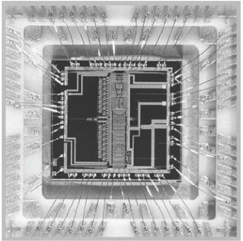
Recover MCU ATtiny88V Software and make the firmware cloning from master attiny88v which will provide the same functions, program from attiny88v memory will be readout by programmer;
The Stack is mainly used for storing temporary data, for storing local variables and for storing return addresses after interrupts and subroutine calls. The Stack Pointer Register always points to the top of the Stack. Note that the Stack is implemented as growing from higher memory locations to lower memory locations when Recover Mcu pic16f628 firmware.
This implies that a Stack PUSH command decreases the Stack Pointer. The Stack Pointer points to the data SRAM Stack area where the Subroutine and Interrupt Stacks are located. This Stack space in the data SRAM must be defined by the program before any subroutine calls are executed or interrupts are enabled.
The Stack Pointer must be set to point above 0x0200. The initial value of the stack pointer is the last address of the internal SRAM. The Stack Pointer is decremented by one when data is pushed onto the Stack with the PUSH instruction, and it is decremented by three when the return address is pushed onto the Stack with subroutine call or interrupt.
The Stack Pointer is incremented by one when data is popped from the Stack with the POP instruction, and it is incremented by three when data is popped from the Stack with return from subroutine RET or return from interrupt RETI after break pic12hv615 Mcu.
The AVR Stack Pointer is implemented as two 8-bit registers in the I/O space. The number of bits actually used is implementation dependent. Note that the data space in some implementations of the AVR architecture is so small that only SPL is needed.
In this case, the SPH Register will not be present. This section describes the general access timing concepts for instruction execution. The AVR CPU is driven by the CPU clock clkCPU, directly generated from the selected clock source for the chip. No internal clock division is used.
Figure 9 shows the parallel instruction fetches and instruction executions enabled by the Harvard architecture and the fast-access Register File concept. This is the basic pipelining concept to obtain up to 1 MIPS per MHz with the corresponding unique results for functions per cost, functions per clocks, and functions per power-unit.
The AVR provides several different interrupt sources. These interrupts and the separate Reset Vector each have a separate program vector in the program memory space. All interrupts are assigned individual enable bits which must be written logic one together with the Global Interrupt Enable bit in the Status Register in order to enable the interrupt.
Depending on the Program Counter value, interrupts may be automatically disabled when Boot Lock bits BLB02 or BLB12 are programmed. This feature improves software security.
The lowest addresses in the program memory space are by default defined as the Reset and Interrupt Vectors. The complete list of vectors is shown in “Interrupts” on page 69. The list also determines the priority levels of the different interrupts. The lower the address the higher is the priority level.
RESET has the highest priority, and next is INT0 – the External Interrupt Request 0. The Interrupt Vectors can be moved to the start of the Boot Flash section by setting the IVSEL bit in the MCU Control Register (MCUCR).
Refer to “Interrupts” on page 69 for more information. The Reset Vector can also be moved to the start of the Boot Flash section by programming the BOOTRST Fuse. When an interrupt occurs, the Global Interrupt Enable I-bit is cleared and all interrupts are disabled.
The user software can write logic one to the I-bit to enable nested inter rupts. All enabled interrupts can then interrupt the current interrupt routine. The I-bit is automatically set when a Return from Interrupt instruction – RETI – is executed.
Posted in Recover Chip |
Tags: recover mcu embedded archive, recover mcu embedded binary, recover mcu embedded code, recover mcu embedded content, recover mcu embedded data, recover mcu embedded eeprom, recover mcu embedded file, recover mcu embedded firmware, recover mcu embedded heximal, recover mcu embedded information, recover mcu embedded memory, recover mcu embedded program |
Comments Closed
ATtiny48: A Small Core in a Wide Package
A small flash array in a wide package is not a contradiction. It is a part chosen for its pin count rather than its memory, and the combination says something about the product: many signals, little logic, no need for a large program.
Those are also the products that are easiest to examine, because the program is small enough to read in full and the pin count makes in-circuit access practical rather than awkward.
Why the mismatch exists
Three reasons appear repeatedly.
Driving a display or a keypad. Dozens of pins, each doing something trivial. The code is a lookup table and a loop, and it fits comfortably in a few kilobytes.
Interfacing many discrete signals. A bank of sensors or relays, each on its own pin, each with a short handler. Pin count is the constraint; memory is not.
Replacing glue logic. A part that reads eight inputs, applies a small truth table, and drives eight outputs. This is the case where the program is genuinely tiny and the package is doing all the work.
In each case the flash is small because the job is small, and the package is wide because the job is parallel.
| Property | Consequence |
|---|---|
| Many pins | In-circuit programming is usually practical |
| Small array | Full read takes seconds, double-reading costs nothing |
| Wide port set | Port configuration describes the product |
| No boot section | One protection field, binary outcome |
What the small array makes easy
A full read of an array this size takes seconds. There is no reason to skip the second pass, no reason to skip page-level comparison, and no reason to accept an unverified image.
More usefully, the whole program can be read rather than sampled. On a few kilobytes, a careful reader can account for every function, and unusual constructs stand out — a hand-written delay loop sized for a specific device, a table with an obvious stride, a checksum constant that matches an external chip.
That is a different activity from analysing a large image, where the work is statistical and the conclusions are probabilistic. Here it is exhaustive, and the conclusions can be certain.
The protection model, unchanged
Nothing about the package affects the protection. Two lock bits, four states, and one erase that clears them along with the array. No boot section, no self-programming path, no second container.
That means the reasoning is short and the outcome is binary: the array is readable, or it is not, and if it is not, the only operation that changes that returns a blank part.
The only thing the wide package changes is access. With twenty-eight pins, the programming interface is much less likely to be fully consumed by other functions, and a header is more likely to exist on the board. In-circuit entry is therefore the norm rather than the exception, which is a real practical advantage over the eight-pin members.
Reading a many-pin, small-memory device
- Supply at the design rail, measured at the socket.
- Signature and fuses. With this many pins, a part configured for an external clock is common — a wide package often accompanies a design that has room for a crystal.
- Lock byte.
- Array read in pages, twice each.
- Map the port accesses: which port is initialised as input, which as output, and in what order.
Step 5 is the one that turns the image into a description of the product. On a device whose purpose is driving many signals, the port configuration is the design. It says which pins are inputs, which are outputs, which have pull-ups enabled, and which are left alone — and that is more informative than the arithmetic in between.
What the pin map tells a customer
For a device that exists to interface with the physical world, the questions are usually about the interface: what does it expect, what does it drive, what are the timing requirements.
All three are answerable from the port configuration plus the code that reads and writes those ports. The memory size stops being interesting at that point, which is the correct outcome: the product’s behaviour is the subject, not its storage.
Related notes
- ATtiny48A and revision behaviour — what changes between dies of the same name.
- ATtiny88 and page boundaries — the larger array in the same package.
- ATtiny25 and shared pins — the opposite end of the package range.
FAQ
Does a wide package mean more memory? No. Memory size and pin count are independent choices in this family.
Is in-circuit programming easier here? Generally yes, because the programming pins are less likely to be fully committed to other functions.
Does the package change the lock bit behaviour? No. The protection model is identical across packages.
Why would a design use such a large package for such a small program? Because the pin count is the requirement and the program is incidental.
Conclusion
A small core in a wide package is a deliberate trade, and it makes examination easier rather than harder. The array fits in a single reading, the pins are accessible, and the port configuration describes the product more directly than its code does. On this kind of device, the interface is the design.
Posted in Recover Chip |
Tags: recover mcu embedded archive, recover mcu embedded code, recover mcu embedded content, recover mcu embedded data, recover mcu embedded eeprom, recover mcu embedded file, recover mcu embedded firmware, recover mcu embedded information, recover mcu embedded memory, recover mcu embedded program |
Comments Closed
ATmega2561V: The Largest Member, and the Same One Fuse
Scale changes many things about a part. A quarter of a megabyte of flash needs a wider program counter, a different page count, and a read that takes long enough to expose supply behaviour that a small part hides. Scale does not change the arbitration that decides whether anything is recoverable.
That arbitration is a single fuse bit. On a part this large it is easy to imagine that the extra memory implies extra rules. It does not. The same erase, the same lock state machine, the same fuse, applied to a bigger array.
What is different at this size
Three engineering consequences, none of them about protection.
The read takes time. A quarter of a megabyte at a conservative clock is minutes, not seconds. Over that window the supply can sag, the part can warm, and a clip can lose contact. Any of those produces a file that is correct at the start and wrong later.
The address space is fully populated. Unlike a smaller member occupying a subset of the same map, this one uses all of it, so an all-FF region in the middle is meaningful rather than a marker of unimplemented memory.
The program counter is three bytes wide. Return addresses, jump targets, and table pointers all carry an extra byte, and code that manipulates the stack directly has to account for it.
What is not different
| Rule | Applies here exactly as elsewhere |
|---|---|
| Lock mode 2 or 3 blocks verification | yes |
| Chip erase is the only way to clear locks | yes |
| Chip erase erases the flash | yes |
| EEPROM survives only if EESAVE allows | yes |
| No interface bypasses the lock byte | yes |
That table is the whole protection story, and it is identical across the family from the smallest member to this one. Familiarity with a small part transfers directly, which is one of the genuine advantages of a family that shares an architecture.
The EEPROM on a part nobody expects to have one
This member has no external memory interface, so there is no external storage to look for. Its EEPROM holds the per-unit data: calibration, identity, counters. A few kilobytes, and usually the most device-specific content in the product.
Because the flash is large and the EEPROM is small, the natural focus is the code. That focus is correct for understanding the product and wrong for understanding the unit. A device that measures or controls something external almost always carries constants in EEPROM that the code reads at start-up; without them, a faithful reproduction still measures wrong.
The fuse that decides whether those constants survive an erase is the same fuse as on every other member. Set for operational reasons — so a firmware update does not wipe calibration — and set more often than not.
Reading a large array reliably
The risks scale with the read time, so the procedure has to as well:
- Supply at the design rail, measured at the socket, with local decoupling.
- Signature, fuses, lock byte — before anything else.
- One page read twice, compared. Establishes margin.
- Full read in passes, verifying each page as it arrives; log any page that fails.
- Re-read the first page at the end and compare with step 3.
Step 5 is the one that catches drift over the duration of the read. It costs one page and it is the only check that covers the whole session rather than one page.
A page that fails verification in step 4 is not a page to average or to accept. It is a page to re-read at lower clock, or at higher supply, until two consecutive reads agree. If they never agree, the die has a marginal region and that fact belongs in the report.
Working out what you have
An all-FF block in the middle of a full-map part is informative. Three explanations, in order of likelihood: the application does not fill its allowance, an update left a gap, or a page failed to program.
The distinction matters for reproduction. A gap from an incomplete build is reproducible as-is; a gap from a failed program will not be, because the device is running code that was never fully written and its behaviour may depend on what the missing page should have contained.
Comparing the gap boundaries against page alignment settles it. A gap that starts and ends on page boundaries is structural. A gap that starts partway through a page came from an interrupted operation.
Related notes
- ATmega1280PV and the three-byte counter — the same counter on a smaller array.
- ATmega1281PV and reconstruction — the other bus-less member.
- ATmega32PA and EESAVE — the fuse’s mechanism explained from the array side.
FAQ
Does a larger flash mean stronger protection? No. The lock bit mechanism is identical. Extra memory is not extra security.
How long does a full read take? Minutes at a conservative clock. Reducing the clock for reliability is almost always the right trade.
Can the EEPROM be read while the part is locked? No. The read commands are refused in lock mode 2 or 3, which is why the erase and its one surviving array matter.
Is a gap in the middle of the image a problem? It is information. Page-aligned gaps are structural; unaligned ones record a failure.
Conclusion
Size is an engineering detail; protection is an architectural constant. This part’s quarter megabyte changes the read time, the pointer width, and the interpretation of empty regions, and it changes nothing about how a locked device is opened or what survives. Reading the fuse byte first answers the only question that cannot be answered later.
Posted in Reverse Engineer Microcontroller |
Tags: recover mcu embedded archive, recover mcu embedded bin, recover mcu embedded code, recover mcu embedded content, recover mcu embedded data, recover mcu embedded eeprom, recover mcu embedded file, recover mcu embedded firmware, recover mcu embedded hex, recover mcu embedded information, recover mcu embedded memory, recover mcu embedded program |
Comments Closed
Recover MCU R5F562T6DDFF Firmware: The Report Is Half the Deliverable
Ask three suppliers for a firmware recovery and you will receive three archives. One contains a hex file and a one-line email. The second contains the same file plus a folder of screenshots. The third contains the same file plus a short document, and the third is the only one that can be used by somebody who was not in the room.
The difference is not extra work in the sense of hours. It is a different idea of what the customer bought. A firmware recovery exists to be relied on, and reliance needs a statement of what was done, what was found and what could not be established. On a thirty-two-bit motor-control part with an option area, a clock tree and a protection setting, the list of things that “could not be established” is not empty, and hiding it is the fastest way to lose a customer three months later.
R5F562T6DDFF#V3 is an RX62T group device: hundred-megahertz core with an FPU, two twelve-bit converter units, six-channel motor timer, QFN-type package field, and a version suffix that identifies a shipping configuration rather than different silicon.
Five sections a report needs
| section | content | why it exists |
|---|---|---|
| scope | device, order code, protection state, what was asked for | fixes the question being answered |
| method | route used, in sequence, with settings | makes the work repeatable |
| evidence | the checks that passed, with values | distinguishes a read from a copy |
| limits | what was not established, and why | prevents false reliance |
| artefacts | files, names, lengths, checksums | proves what was delivered |
The fourth row is the one that gets omitted and the one that matters most. A report without a limits section is not more confident; it is less honest, and the omission surfaces at the worst possible moment — when a rebuilt unit misbehaves and nobody knows whether the image or the configuration is at fault.
What belongs in the limits section on this part
Four items, on a typical job.
The clock. The crystal fitted to the board was not measured, so the frequencies stated in the report are the ones the code programs rather than the ones the hardware produces.
The external components. Anything the firmware talks to over a bus is outside the recovery, and its behaviour is assumed rather than known.
The toolchain. A rebuild is empirically equivalent, not provably identical, unless the original compiler version was established.
And the endurance state, where a data region was recovered: the wear level is reported, and the consequence of that wear is the customer’s decision rather than the supplier’s.
Stating those four costs a paragraph and removes an entire category of later dispute.
The reproducibility test
A good test of a report is whether another laboratory could repeat the work from it and get the same bytes.
Three things have to be present for the answer to be yes. The route has to be named precisely enough to follow — not “boot mode” but boot mode with the mode-pin sequence, the baud rate and the protocol version. The settings have to be recorded, including the settings that did not work, because a later engineer who tries the failing setting first will conclude the report is wrong. And the verification values have to be present, so that the second laboratory can compare rather than merely compare sizes.
A report that passes that test is also a report that answers a challenge, which on disputed work is worth more than the technical content.
Chain of custody, when the unit is evidence
A subset of recoveries are not engineering exercises. A unit from a failed product in a liability dispute, or from a competitor’s device in a patent matter, has to be handled in a way that survives a question about who did what to it.
Three practices cover it. Record the unit’s identifiers on arrival, with photographs, before any work. Record every destructive step with a timestamp, because “we opened it” is a different statement from “we opened it after the electrical tests on this date”. And keep the original state recoverable where possible — the first read, the first image, unmodified, before any decoding or repair.
That last practice is easy and frequently skipped: engineers repair a byte-swapped image and save over it, and the evidence of the swap disappears. Keep the raw read and write the corrected version to a new file.
What customers do with these documents
Three uses, and none of them is technical.
An audit, where an inspector wants to know that the firmware in a certified product matches the one that was certified. The report’s evidence section is the answer.
An insurance or warranty claim, where the question is whether a unit failed because of a defect or because of an interrupted update. The block classification from a field-unit read answers that.
And a succession problem: a product whose original developer has left, whose firmware exists only on a chip. The report plus the artefacts is the only asset that survives.
For the block classification that answers the interrupted-update question, R5F562T7DDFF flash covers the archaeology. For the session-level evidence that a behaviour question needs rather than a copy, R5F562T6ADFF binary covers the second access route. For the configuration that must appear in the evidence section, R5F562TABDFF program deals with the option area. And for the timing statement that belongs in the limits, R5F562T6DDFF program covers the clock tree.
FAQ
Is a report required, or is it a courtesy? It is the part of the delivery that makes the rest usable. Without it the customer has files they cannot defend.
How long should it be? Two to five pages for a routine recovery. The length is set by the limits section, not by the method section.
Should unsuccessful routes be documented? Yes. A record of what failed is the most reused content in the whole document.
The short version
Five sections: scope, method, evidence, limits, artefacts. The limits section protects both sides, the method section makes the work repeatable, and the evidence section answers a challenge. Keep the raw read unmodified, and state the clock, the external assumptions and the toolchain as assumptions rather than letting them pass as facts.