 Recover MCU ATmega861A Code
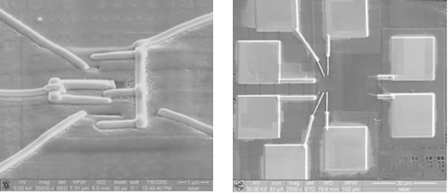
Recover MCU ATmega861A is a process to unlock microcontroller ATmega861A secured flash and eeprom memory, and then readout the code from ATmega861A;
The EEPROM Read Enable Signal EERE is the read strobe to the EEPROM. When the correct address is set up in the EEAR Register, the EERE bit must be written to a logic one to trigger the EEPROM read. The EEPROM read access takes one instruction, and the requested data is available immediately.
When the EEPROM is read, the CPU is halted for four cycles before the next instruction is executed. The user should poll the EEPE bit before starting the read operation. If a write operation is in progress, it is neither possible to read the EEPROM, nor to change the EEAR Register if Reverse engineering microcontroller attiny85 flash.
The calibrated Oscillator is used to time the EEPROM accesses. Table 3 lists the typical programming time for EEPROM access from the CPU. The following code examples show one assembly and one C function for writing to the EEPROM. The examples assume that interrupts are controlled (e.g. by disabling interrupts globally) so that no interrupts will occur during execution of these functions.
The examples also assume that no Flash Boot Loader is present in the software. If such code is present, the EEPROM write function must also wait for any ongoing SPM command to finish. The next code examples show assembly and C functions for reading the EEPROM after break MCU attiny2313 code.
The examples assume that interrupts are controlled so that no interrupts will occur during execution of these functions. During periods of low VCC, the EEPROM data can be corrupted because the supply voltage is too low for the CPU and the EEPROM to operate properly.
These issues are the same as for board level systems using EEPROM, and the same design solutions should be applied. An EEPROM data corruption can be caused by two situations when the voltage is too low. First, a regular write sequence to the EEPROM requires a minimum voltage to operate correctly when Reverse engineering microcontroller attiny4313 code.
Secondly, the CPU itself can execute instructions incorrectly, if the supply voltage is too low. EEPROM data corruption can easily be avoided by following this design recommendation:
Keep the AVR RESET active (low) during periods of insufficient power supply voltage. This can be done by enabling the internal Brown-out Detector (BOD). If the detection level of the internal BOD does not match the needed detection level, an external low VCC reset Protection circuit can be used.
If a reset occurs while a write operation is in progress, the write operation will be completed provided that the power supply voltage is sufficient.