Posts Tagged ‘decap ic bin’
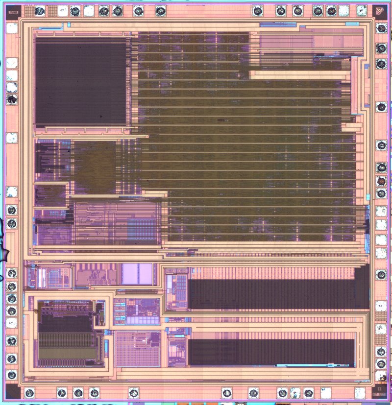
 Decap IC PIC16C55 Eeprom
Decap IC PIC16C55 Eeprom and extract mcu pic16c55 heximal from flash memory, and clone firmware to new microcontroller pic16c55 to provide the same functions;

Setting both UMSELn1:0 bits to one enables the USART in MSPIM logic. In this mode of operation the SPI master control logic takes direct control over the USART resources.
These resources include the transmitter and receiver shift register and buffers, and the baud rate generator. The parity generator and checker, the data and clock recovery logic, and the RX and TX control logic is disabled if recover mcu pic16f873 hex.
The USART RX and TX control logic is replaced by a common SPI transfer control logic. However, the pin control logic and interrupt generation logic is identical in both modes of operation.
The I/O register locations are the same in both modes. However, some of the functionality of the control registers changes when using MSPIM before recover mcu dspic30f6013 firmware.
The Clock Generation logic generates the base clock for the Transmitter and Receiver. For USART MSPIM mode of operation only internal clock generation (i.e. master operation) is supported.
The Data Direction Register for the XCKn pin (DDR_XCKn) must therefore be set to one (i.e. as output) for the USART in MSPIM to operate correctly when break mcu at89c5131a IC.
Preferably the DDR_XCKn should be set up before the USART in MSPIM is enabled (i.e. TXENn and RXENn bit set to one). The internal clock generation used in MSPIM mode is identical to the USART synchronous master mode.
The baud rate or UBRRn setting can therefore be calculated using the same equations, see Table 110: Table 110. Equations for Calculating Baud Rate Register Setting There are four combinations of XCKn (SCK) phase and polarity with respect to serial data, which are determined by control bits UCPHAn and UCPOLn.
The data transfer timing diagrams are shown in Figure 90. Data bits are shifted out and latched in on opposite edges of the XCKn signal, ensuring sufficient time for data signals to stabilize.
The UCPOLn and UCPHAn functionality is summarized in Table 111. Note that changing the setting of any of these bits will corrupt all ongoing communication for both the Receiver and Transmitter.
 Decap IC PIC16C54A Heximal file
Decap IC PIC16C54A and clone microcomputer pic16c54a memory content, and read mcu pic16c54a Heximal file out from its flash and eeprom memory;

Bit 4 – RXENn: Receiver Enable n
Writing this bit to one enables the USART Receiver. The Receiver will override normal port operation for the RxDn pin when enabled. Disabling the Receiver will flush the receive buffer invalidating the FEn, DORn, and UPEn Flags when copy microcontroller at89c51re2 bin file.
Bit 3 – TXENn: Transmitter Enable n
Writing this bit to one enables the USART Transmitter. The Transmitter will override normal port operation for the TxDn pin when enabled.
The disabling of the Transmitter (writing TXENn to zero) will not become effective until ongoing and pending transmissions are completed, i.e., when the Transmit Shift Register and Transmit Buffer Register do not contain data to be transmitted. When disabled, the Transmitter will no longer override the TxDn port.
Bit 2 – UCSZn2: Character Size n
The UCSZn2 bits combined with the UCSZn1:0 bit in UCSRnC sets the number of data bits (Character SiZe) in a frame the Receiver and Transmitter use after recover IC c8051f340 hex file.
Bit 1 – RXB8n: Receive Data Bit 8 n
RXB8n is the ninth data bit of the received character when operating with serial frames with nine data bits. Must be decap before decaping the low bits from UDRn when break IC STM32F101C4T6 hex file.
Bit 0 – TXB8n: Transmit Data Bit 8 n
TXB8n is the ninth data bit in the character to be transmitted when operating with serial frames with nine data bits. Must be written before writing the low bits to UDRn.
Bits 7:6 – UMSELn1:0 USART Mode Select
These bits select the mode of operation of the USARTn as shown in Table 101..
Bits 5:4 – UPMn1:0: Parity Mode
These bits enable and set type of parity generation and check. If enabled, the Transmitter will automatically generate and send the parity of the transmitted data bits within each frame.
The Receiver will generate a parity value for the incoming data and compare it to the UPMn setting. If a mismatch is detected, the UPEn Flag in UCSRnA will be set.
Bit 3 – USBSn: Stop Bit Select
This bit selects the number of stop bits to be inserted by the Transmitter. The Receiver ignores this setting.