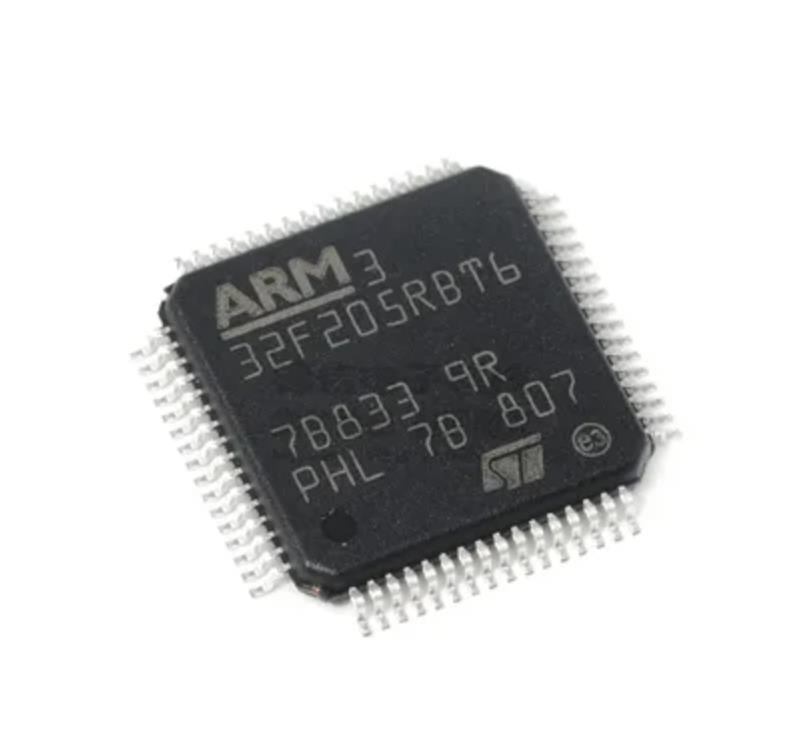
 Restoring ARM STM32F205RE MCU Flash Firmware
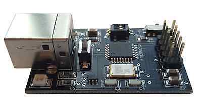
Restoring ARM STM32F205RE MCU Flash Firmware starts from decrypt ARM STM32F205RE microcontroller flash memory program and then readout embedded code from microprocessor stm32f205re flash memory;
Restoring ARM STM32F205RE MCU Flash Firmware starts from decrypt ARM STM32F205RE microcontroller flash memory program and then readout embedded code from microprocessor stm32f205re flash memory
For the LQFP100 package, only FSMC Bank1 or Bank2 are Bank1 can only support a multiplexed NOR/PSRAM memory using the NE1 Chip Select. Bank2 can only support a 16- or 8-bit NAND Flash memory using the NCE2 Chip Select. The interrupt line cannot be used since Port G is not available in this package.
The SPI2 and SPI3 interfaces give the flexibility to work in an exclusive way in either the SPI mode or the I2S audio on devices in WLCSP64+2 package for arm stm32f205rc mcu flash memory heximal recovery, if IRROFF is set to VDD, the supply voltage can drop to 7 V when the device operates in the 0 to 70 °C temperature range using an external power supply supervisor.
взломать защищенный mcu stm32f205ret6 и скопировать программу flash heximal memory из прошивки микропроцессора stm32f205ret6
The STM32F205xx constitute the STM32F20x family, whose members are fully pin-to-pin, software and feature compatible, allowing the user to try different memory densities and peripherals for a greater degree of freedom during the development cycle.
The STM32F205xx and STM32F207xx devices maintain a close compatibility with the whole STM32F10xxx family. All functional pins are pin-to-pin compatible. The STM32F205xx and STM32F207xx, however, are not drop-in replacements for the STM32F10xxx devices: the two families do not have the same power scheme, and so their power pins are different. Nonetheless, transition from the STM32F10xxx to the STM32F20x family remains simple as only a few pins are impacted.
ARM STM32F205RC Microcontroller Flash Memory Heximal Recovery
ARM STM32F205RC Microcontroller Flash Memory Heximal Recovery starts from decrypting arm mcu stm32f205rc embedded memory program and then clone flash memory code to new mcu stm32f205rc;

ARM STM32F205RC Microcontroller Flash Memory Heximal Recovery starts from decrypting arm mcu stm32f205rc embedded memory program and then clone flash memory code to new mcu stm32f205rc;
The STM32F205xx and STM32F207xx devices operate in the –40 to +105 °C temperature range from a 1.8 V to 3.6 V power supply. On devices in WLCSP64+2 package, if IRROFF is set to VDD, the supply voltage can drop to 1.7 V when the device operates in the 0 to
70 °C temperature range using an external power supply supervisor (see Section 3.16).
A comprehensive set of power-saving modes enables the design of low-power applications.
STM32F205xx and STM32F207xx devices are offered in various packages, ranging from 64 to 176 pins. The set of included peripherals changes with the chosen device when recovering ic chip stm32f107rct6 code.These features make the STM32F205xx and STM32F207xx microcontroller family suitable for a wide range of applications:
- Motor drive and application control
- Medical equipment
- Industrial applications: PLC, inverters, circuit breakers
- Printers, and scanners
- Alarm systems, video intercom, and HVAC
- Home audio appliances
- For the LQFP100 package, only FSMC Bank1 or Bank2 are Bank1 can only support a multiplexed NOR/PSRAM memory using the NE1 Chip Select. Bank2 can only support a 16- or 8-bit NAND Flash memory using the NCE2 Chip Select. The interrupt line cannot be used since Port G is not available in this package.
- The SPI2 and SPI3 interfaces give the flexibility to work in an exclusive way in either the SPI mode or the I2S audio when breaking stm32f101c4 binary file;
- On devices in WLCSP64+2 package, if IRROFF is set to VDD, the supply voltage can drop to 7 V when the device operates in the 0 to 70 °C temperature range using an external power supply supervisor (see Section 3.16).
разблокировать микропроцессор STM32F205RCt6 и клонировать прошивку флэш-памяти на новый микроконтроллер STM32F205RCt6
Break ARM STM32F205RB MCU Flash Memory
Break ARM STM32F205RB MCU Flash Memory and read embedded firmware out from STM32F205RB microcontroller, copy arm cortex3 stm32f205rb program binary to new microprocessor;
Break ARM STM32F205RB MCU Flash Memory and read embedded firmware out from STM32F205RB microcontroller, copy arm cortex3 stm32f205rb program binary to new microprocessor
The STM32F20x family is based on the high-performance Arm® Cortex®-M3 32-bit RISC core operating at a frequency of up to 120 MHz to recover microcontroller stm32f105rc flash memory content. The family incorporates high-speed embedded memories (Flash memory up to 1 Mbyte, up to 128 Kbytes of system SRAM), up to 4 Kbytes of backup SRAM, and an extensive range of enhanced I/Os and peripherals connected to two APB buses, three AHB buses and a 32-bit multi-AHB bus matrix.
The devices also feature an adaptive real-time memory accelerator (ART Accelerator™) that allows to achieve a performance equivalent to 0 wait state program execution from Flash memory at a CPU frequency up to 120 MHz. This performance has been validated using the CoreMark® benchmark.
разблокировать защищенный предохранитель микропроцессора stm32f205rbt6 и скопировать шестнадцатеричную программу прошивки из флэш-памяти микрокомпьютера stm32f205rbt6
All devices offer three 12-bit ADCs, two DACs, a low-power RTC, twelve general-purpose 16-bit timers including two PWM timers for motor control, two general-purpose 32-bit timers. a true number random generator (RNG). They also feature standard and advanced communication interfaces when breaking off stm32f101c4 flash memory firmware. New advanced peripherals include an SDIO, an enhanced flexible static memory control (FSMC) interface (for devices offered in packages of 100 pins and more), and a camera interface for CMOS sensors. The devices also feature standard peripherals.
- Up to three I2Cs
- Three SPIs, two I2 To achieve audio class accuracy, the I2S peripherals can be clocked via a dedicated internal audio PLL or via an external PLL to allow synchronization.
- Four USARTs and two UARTs
- A USB OTG high-speed with full-speed capability (with the ULPI)
- A second USB OTG (full-speed)
- Two CANs
- An SDIO interface
- Ethernet and camera interface available on STM32F207xx devices
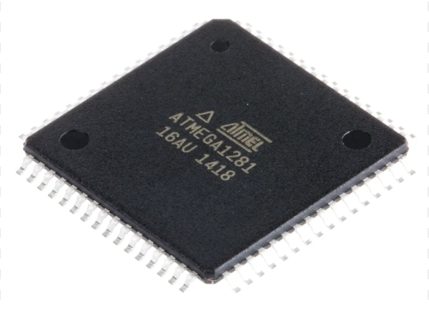
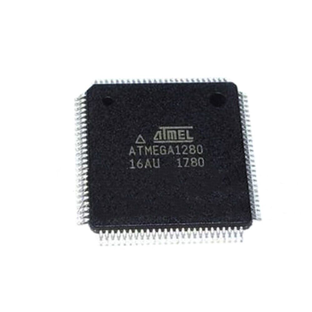
Locked Microcontroller ATmega1281 Flash Memory Breaking
Locked Microcontroller ATmega1281 Flash Memory Breaking is a process to unlock microprocessor atmega1281 flash fuse bit and release software program from its memory and then copy firmware heximal to new mcu atmega1281 avr chip;
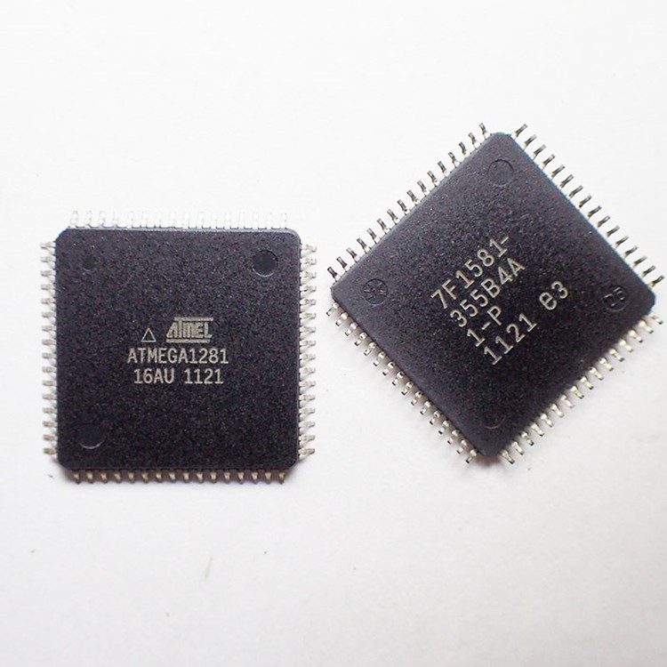
Locked Microcontroller ATmega1281 Flash Memory Breaking is a process to unlock microprocessor atmega1281 flash fuse bit and release software program from its memory and then copy firmware heximal to new mcu atmega1281 avr chip;
This section discusses the AVR core architecture in general. The main function of the CPU core is to ensure cor- rect program execution. The CPU must therefore be able to access memories, perform calculations, control peripherals, and handle interrupts.
In order to maximize performance and parallelism, the AVR uses a Harvard architecture – with separate memories and buses for program and data. Instructions in the program memory are executed with a single level pipelining by reverse engineering microcontroller atmega1281 program. While one instruction is being executed, the next instruction is pre-fetched from the program memory. This concept enables instructions to be executed in every clock cycle. The program memory is In-System Reprogrammable Flash memory.
crack atmega1281 mcu flash protective system and extract embedded binary file from flash memory
The fast-access Register File contains 32 × 8-bit general purpose working registers with a single clock cycle access time. This allows single-cycle Arithmetic Logic Unit (ALU) operation. In a typical ALU operation, two operands are output from the Register File, the operation is executed, and the result is stored back in the Register File– in one clock cycle by reverse engineering atmega1281 mcu firmware.
Desbloquee los datos del programa del controlador Microchip ATMEGA1280V y lea la memoria flash mcu atmega1280v heximal, el contenido flash original del microcontrolador avr atmega1280v se decodificará
Six of the 32 registers can be used as three 16-bit indirect address register pointers for Data Space addressing – enabling efficient address calculations. One of the these address pointers can also be used as an address pointer for look up tables in Flash program memory. These added function registers are the 16-bit X-, Y-, and Z-register, described later in this section.
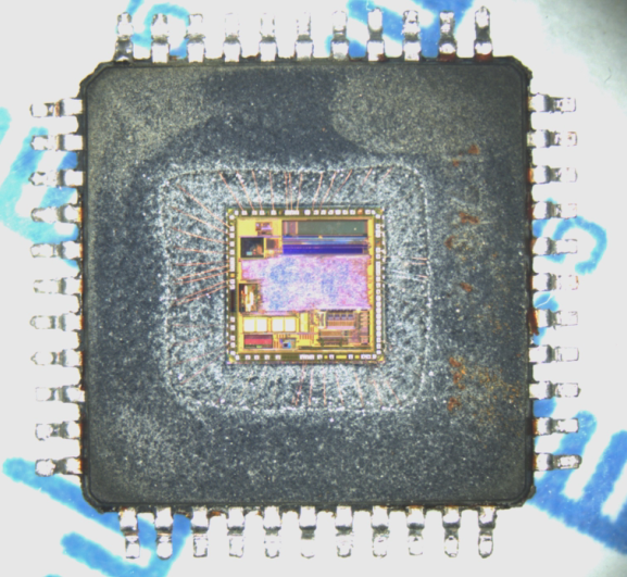
Unlock Microchip ATMEGA1280V Controller Program Data
Unlock Microchip ATMEGA1280V Controller Program Data and read mcu atmega1280v flash memory heximal, original avr microcontroller atmega1280v flash content will be decoding;
Unlock Microchip ATMEGA1280V Controller Program Data and read mcu atmega1280v flash memory heximal, original avr microcontroller atmega1280v flash content will be decoding
Port G is a 6-bit bi-directional I/O port with internal pull-up resistors (selected for each bit). The Port G output buffers have symmetrical drive characteristics with both high sink and source capability. As inputs, Port G pins that are externally pulled low will source current if the pull-up resistors are activated when breaking ic chip atmega1280v flash binary. The Port G pins are tri-stated when a reset condition becomes active, even if the clock is not running. Port G also serves the functions of various special features of the Atmel ATmega1280v as listed on page 72.
Desbloquee los datos del programa del controlador Microchip ATMEGA1280V y lea la memoria flash mcu atmega1280v heximal, el contenido flash original del microcontrolador avr atmega1280v se decodificará
Port H is a 8-bit bi-directional I/O port with internal pull-up resistors (selected for each bit). The Port H output buffers have symmetrical drive characteristics with both high sink and source capability. As inputs, Port H pins that are externally pulled low will source current if the pull-up resistors are activated. The Port H pins are tri-stated when a reset condition becomes active when recover microprocessor atmega1280v flash memory file, even if the clock is not running. Port H also serves the functions of various special features of the ATmega3250/6450 as listed on page 72.
clone atmega1280v microprocessor flash heximal and copy firmware code to new atmega1280v microcontroller and encrypt the chip
Port J is a 7-bit bi-directional I/O port with internal pull-up resistors (selected for each bit). The Port J output buffers have symmetrical drive characteristics with both high sink and source capa- bility. As inputs, Port J pins that are externally pulled low will source current if the pull-up resistors are activated. The Port J pins are tri-stated when a reset condition becomes active, even if the clock is not running.
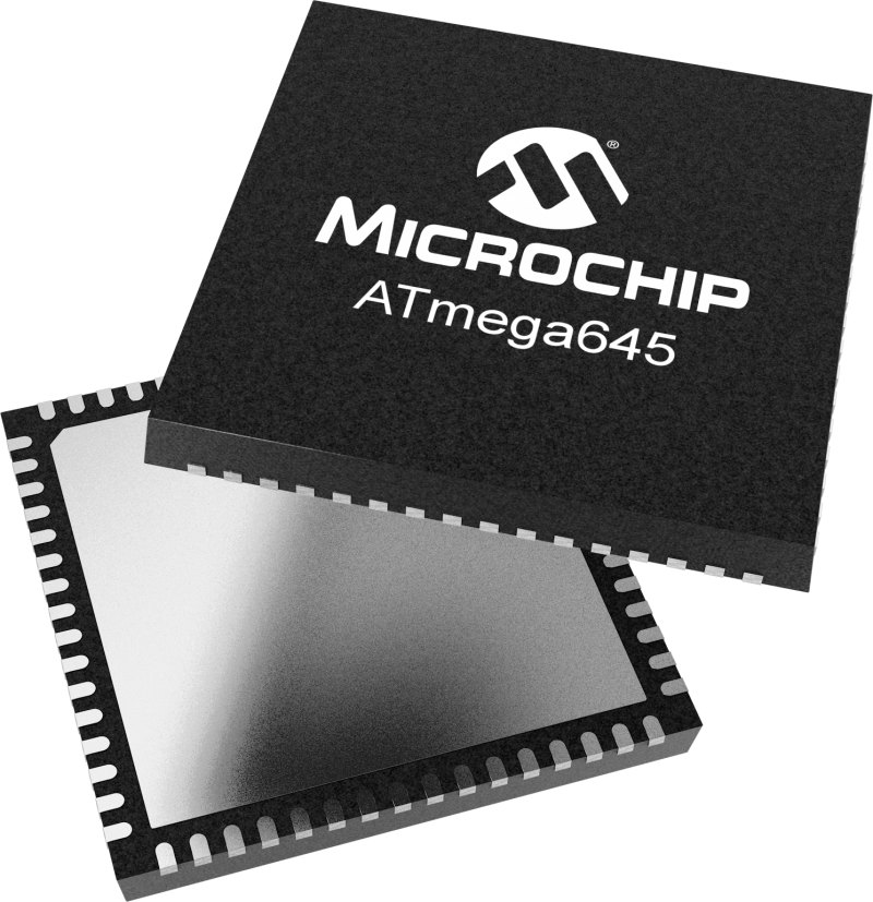
Microchip ATmega1280 Locked Microcontroller Heximal Restoration
Microchip ATmega1280 Locked Microcontroller Heximal Restoration needs to unlock mcu atmega1280 flash memory and then read out firmware program from atmega1280 flash and eeprom memory;
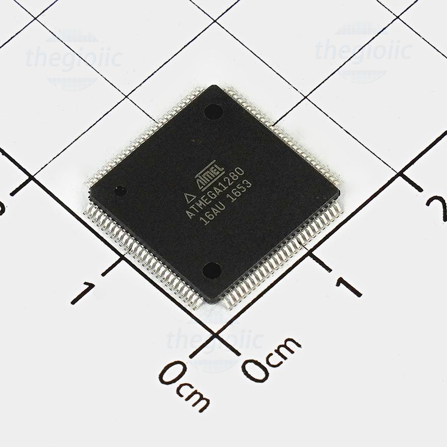
Microchip ATmega1280 Locked Microcontroller Heximal Restoration needs to unlock mcu atmega1280 flash memory and then read out firmware program from atmega1280 flash and eeprom memory
Port H is a 8-bit bi-directional I/O port with internal pull-up resistors (selected for each bit). The Port H output buf- fers have symmetrical drive characteristics with both high sink and source capability. As inputs, Port H pins that are externally pulled low will source current if the pull-up resistors are activated. The Port H pins are tri-stated when a reset condition becomes active, even if the clock is not running.
La restauración heximal del microcontrolador bloqueado ATmega1280 de Microchip necesita desbloquear la memoria flash mcu atmega1280 y luego leer el programa de firmware de la memoria flash atmega1280 y eeprom;
Port J is a 8-bit bi-directional I/O port with internal pull-up resistors (selected for each bit). The Port J output buffers have symmetrical drive characteristics with both high sink and source capability. As inputs, Port J pins that are externally pulled low will source current if the pull-up resistors are activated. The Port J pins are tri-stated when a reset condition becomes active, even if the clock is not running.
crack atmel atmega1280 mcu fuse bit and readout embedded firmware from microcontroller atmega1280 flash and eeprom memory
Port K is a 8-bit bi-directional I/O port with internal pull-up resistors (selected for each bit). The Port K output buffers have symmetrical drive characteristics with both high sink and source capability. As inputs, Port K pins that are externally pulled low will source current if the pull-up resistors are activated. The Port K pins are tri-stated when a reset condition becomes active, even if the clock is not running.
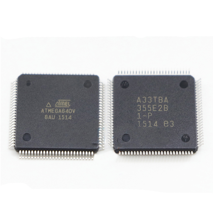
Secured Microchip ATMEGA640V MCU Flash Program Recovery
Secured Microchip ATMEGA640V MCU Flash Program Recovery needs to firstly crack mcu atmel atmega640v protective system and read atmega640v microcontroller flash memory content out from it;
Secured Microchip ATMEGA640V MCU Flash Program Recovery needs to firstly crack mcu atmel atmega640v protective system and read atmega640v microcontroller flash memory content out from it;
Port A is an 8-bit bi-directional I/O port with internal pull-up resistors (selected for each bit). The Port A output buf- fers have symmetrical drive characteristics with both high sink and source capability. As inputs, Port A pins that are externally pulled low will source current if the pull-up resistors are activated to recover atmega640v microcontroller flash firmware. The Port A pins are tri-stated when a reset condition becomes active, even if the clock is not running.
microchip seguro atmega640v mcu flash program recovery necesita primero descifrar el sistema de protección mcu atmel atmega640v y leer el contenido de la memoria flash del microcontrolador atmega640v.
Port B is an 8-bit bi-directional I/O port with internal pull-up resistors (selected for each bit). The Port B output buf- fers have symmetrical drive characteristics with both high sink and source capability. As inputs, Port B pins that are externally pulled low will source current if the pull-up resistors are activated. The Port B pins are tri-stated when a reset condition becomes active, even if the clock is not running.
recover atmega640v microprocessor flash memory content and copy firmware to new mcu chip atmega640v
Port C is an 8-bit bi-directional I/O port with internal pull-up resistors (selected for each bit). The Port C output buf- fers have symmetrical drive characteristics with both high sink and source capability after breaking ic chip atmega640v flash protection. As inputs, Port C pins that are externally pulled low will source current if the pull-up resistors are activated. The Port C pins are tri-stated when a reset condition becomes active, even if the clock is not running.
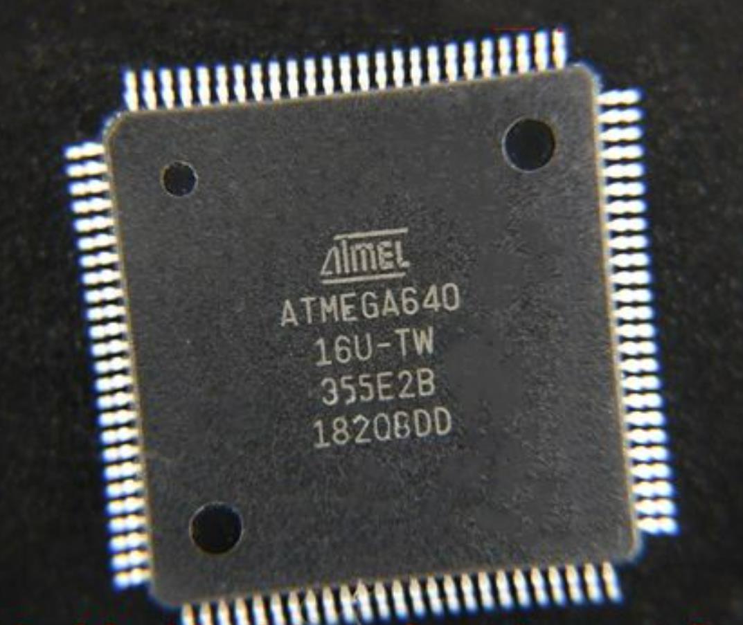
Protected ATMEGA640 MCU Chip Binary Restoration
Protected ATMEGA640 MCU Chip Binary Restoration is a process to unlock secured microcontroller atmega640 firmware from its flash memory and readout microprocessor atmega640 chipset flash and eeprom software data;
Protected ATMEGA640 MCU Chip Binary Restoration is a process to unlock secured microcontroller atmega640 firmware from its flash memory and readout microprocessor atmega640 chipset flash and eeprom software data;
The device is manufactured using the Microchip high-density nonvolatile memory technology. The On-chip ISP Flash allows the program memory to be reprogrammed in-system through an SPI serial interface, by a conventional nonvolatile memory programmer, or by an On-chip Boot program running on the AVR core.
La restauración binaria del chip ATMEGA640 MCU protegido es un proceso para desbloquear el firmware seguro del microcontrolador atmega640 de su memoria flash y leer los datos del software flash y eeprom del chipset atmega640 del microprocesador;
The boot program can use any interface to download the application program in the application Flash memory. Software in the Boot Flash section will continue to run while the Application Flash section is updated while reverse engineering atmega640 microcontroller fuse bit, providing true Read- While-Write operation. By combining an 8-bit RISC CPU with In-System Self-Programmable Flash on a monolithic chip, the ATmega640v is a powerful microcontroller that provides a highly flexible and cost effective solution to many embedded control applications.
crack atmega640 secured mcu fuse bit and readout embedded firmware from flash memory
The ATmega640v AVR is supported with a full suite of program and system development tools including: C compilers, macro assemblers, program debugger/simulators, in-circuit emulators, and evaluation kits. Each device in the ATmega640v family differs only in memory size and number of pins to recover mcu chip atmega640 heximal from flash memory. Table 2-1 summarizes the different configurations for the six devices.
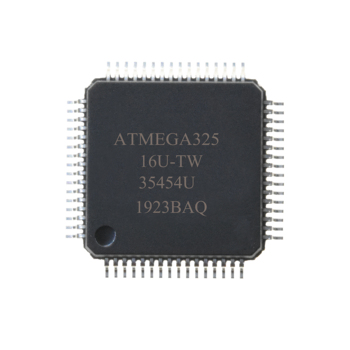
Reverse Protected ATMEGA645 MCU Heximal
Reverse Protected ATMEGA645 MCU Heximal is a process to readout chip atmega645 firmware from its flash and eeprom after attack locked microcontroller atmega645 protective system;
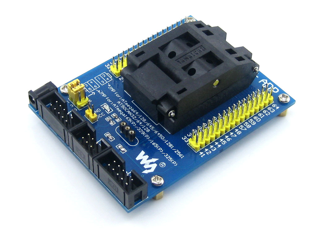
Reverse Protected ATMEGA645 MCU Heximal is a process to readout chip atmega645 firmware from its flash and eeprom after attack locked microcontroller atmega645 protective system
Atmel offers the QTouch® library for embedding capacitive touch buttons, sliders and wheels- functionality into AVR microcontrollers. The patented charge-transfer signal acquisition offersrobust sensing and includes fully debounced reporting of touch keys and includes Adjacent KeySuppression® (AKS™) technology for unambiguous detection of key events to copy chip atmega645 mcu file. The easy-to-use QTouch Suite toolchain allows you to explore, develop and debug your own touch applications.

atmega645 mcu protegido inversamente heximal es un proceso para leer el firmware del chip atmega645 desde su flash y eeprom después de un ataque bloqueado sistema de protección del microcontrolador atmega645;
The device is manufactured using Atmel’s high density non-volatile memory technology. The On-chip In-System re-Programmable (ISP) Flash allows the program memory to be repro- grammed In-System through an SPI serial interface, by a conventional non-volatile memory programmer, or by an On-chip Boot program running on the AVR core. The Boot program can use any interface to download the application program in the Application Flash memory.
decode secured mcu chip atmega645 flash memory and copy its binary
Software in the Boot Flash section will continue to run while the Application Flash section is updated, providing true Read-While-Write operation. By combining an 8-bit RISC CPU with In-System Self-Programmable Flash on a monolithic chip, the Atmel Atmel ATmega645 is a powerful microcontroller that provides a highly flexible and cost effective solution to many embedded control applications.
The Atmel ATmega325/3250/645/6450 is supported with a full suite of program and system development tools including: C Compilers, Macro Assemblers, Program Debugger/Simulators, In-Circuit Emulators, and Evaluation kits.
Break Locked Microcontroller ATMEGA645V Flash Memory
Break Locked Microcontroller ATMEGA645V Flash Memory will help engineer to recover atmega645v flash embedded heximal, the content inside its flash and eeprom can be readout;
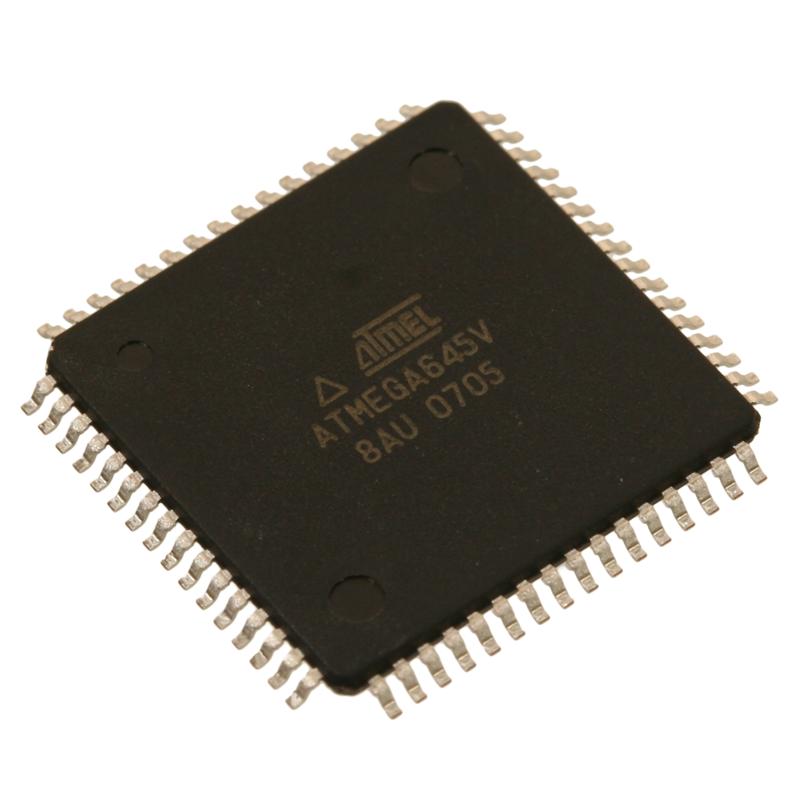
Break Locked Microcontroller ATMEGA645V Flash Memory will help engineer to recover atmega645v flash embedded heximal, the content inside its flash and eeprom can be readout
The Atmel ATmega325/3250/645/6450 provides the following features: 32/64K bytes of In-Sys- tem Programmable Flash with Read-While-Write capabilities, 1/2K bytes EEPROM, 2/4K byte SRAM, 54/69 general purpose I/O lines, 32 general purpose working registers, a JTAG interface for Boundary-scan, On-chip Debugging support and programming, three flexible Timer/Counters with compare modes when recover chipset atmega645v heximal file, internal and external interrupts, a serial programmable USART, Universal Serial Interface with Start Condition Detector, an 8-channel, 10-bit ADC, a programmable Watchdog Timer with internal Oscillator, an SPI serial port, and five software selectable power saving modes.
romper bloqueado microcontrolador ATMEGA 645Z memoria flash ayudará al ingeniero a recuperar atmega 645v flash incrustado heximal, el contenido dentro de su flash y eeprom se puede leer;
The Idle mode stops the CPU while allowing the SRAM, Timer/Counters, SPI port, and interrupt system to continue functioning. The Power-down mode saves the register contents but freezes the Oscillator, disabling all other chip functions until the next interrupt or hardware reset. In Power-save mode, the asynchronous timer will continue to run, allowing the user to maintain a timer base while the rest of the device is sleeping.
crack atmega645v mcu chip and dump embedded firmware from its flash and eeprom memory
The ADC Noise Reduction mode stops the CPU and all I/O modules except asynchronous timer and ADC to minimize switching noise during ADC conversions by reverse engineering atmega644a flash firmware. In Standby mode, the crystal/resonator Oscillator is running while the rest of the device is sleeping. This allows very fast start-up combined with low- power consumption.