 Encrypted ATMEL ATMEGA128A MCU Flash Decoding
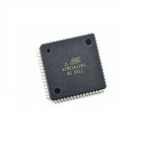
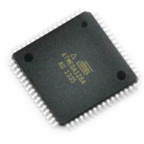
Encrypted ATMEL ATMEGA128A MCU Flash Decoding will help engineer to copy atmega128a microcontroller flash heximal file out after readout atmega128a microprocessor’s content software from its flash and eeprom memory;
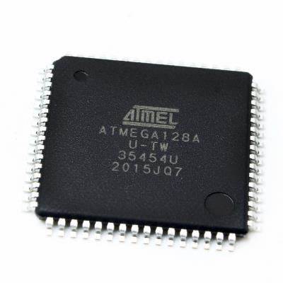
Encrypted ATMEL ATMEGA128A MCU Flash Decoding will help engineer to copy atmega128a microcontroller flash heximal file out after readout atmega128a microprocessor’s content software from its flash and eeprom memory
In this mode, the Watchdog Timer is always enabled, and the WDE bit will always read as one. A timed sequence is needed when changing the Watchdog Time-out period. To change the Watchdog Time-out, the following procedure must be followed:
- In the same operation, write a logical one to WDCE and WDE. Even though the WDE always is set, the WDE must be written to one to start the timed sequence
Within the next four clock cycles, in the same operation, write the WDP bits as desired, but with the WDCE bit cleared. The value written to the WDE bit is irrelevant to break atmega128a mcu fuse bit inside the flash memory.
La decodificación flash MCU ATMEL ATMEGA128A cifrada ayudará al ingeniero a copiar el archivo heximal flash del microcontrolador atmega128a después de leer el software de contenido del microprocesador atmega128a de su memoria flash y eeprom
This section describes the specifics of the interrupt handling performed by the ATmega8. For a general explanation of the AVR interrupt handling, refer to “Reset and Interrupt Handling” on page 14.
Table 19 on page 47 shows reset and Interrupt Vectors placement for the various combinations of BOOTRST and IVSEL settings. If the program never enables an interrupt source, the Interrupt Vectors are not used, and regular program code can be placed at these locations. This is also the case if the Reset Vector is in the Application section while the Interrupt Vectors are in the boot section or vice versa to break atmega128a ic chip flash memory.
attack atmega128a microcontroller fuse bit and extract atmega128a source code
- When the BOOTRST Fuse is programmed, the device will jump to the Boot Loader address at reset, see “Boot Loader Support – Read-While-Write Self-Programming” on page 202
- When the IVSEL bit in GICR is set, Interrupt Vectors will be moved to the start of the boot Flash The address of each Interrupt Vector will then be the address in this table added to the start address of the boot Flash section;
- The Boot Reset Address is shown in Table 82 on page 213. For the BOOTRST Fuse “1” means unprogrammed while “0” means programmed
The most typical and general program setup for the Reset and Interrupt Vector Addresses in ATmega128A is:
| addressLabels | Code | Comments | ||
| $000 | rjmp | RESET | ; Reset Handler | |
| $001 | rjmp | EXT_INT0 | ; IRQ0 Handler | |
| $002 | rjmp | EXT_INT1 | ; IRQ1 Handler | |
| $003 | rjmp | TIM2_COMP | ; Timer2 Compare Handler | |
| $004 | rjmp | TIM2_OVF | ; Timer2 Overflow Handler | |
| $005 | rjmp | TIM1_CAPT | ; Timer1 Capture Handler | |
| $006 | rjmp | TIM1_COMPA | ; Timer1 CompareA Handler | |
| $007 | rjmp | TIM1_COMPB | ; Timer1 CompareB Handler | |
| $008 | rjmp | TIM1_OVF | ; Timer1 Overflow Handler | |
| $009 | rjmp | TIM0_OVF | ; Timer0 Overflow Handler | |
| $00a | rjmp | SPI_STC | ; SPI Transfer Complete Handler | |
| $00b | rjmp | USART_RXC | ; USART RX Complete Handler | |
| $00c | rjmp | USART_UDRE | ; UDR Empty Handler | |
| $00d | rjmp | USART_TXC | ; USART TX Complete Handler | |
| $00e | rjmp | ADC | ; ADC Conversion Complete Handler | |
| $00f | rjmp | EE_RDY | ; EEPROM Ready Handler | |
| $010 | rjmp | ANA_COMP | ; Analog Comparator Handler | |
| $011 | rjmp | TWSI | ; Two-wire Serial Interface Handler | |
| $012 | rjmp | SPM_RDY | ; Store Program Memory Ready Handler | |
| ; | ||||
| $013 | RESET: ldi | r16,high(RAMEND); Main program start | ||
| $014 | out | SPH,r16 ; Set Stack Pointer to top of RAM | ||
| $015 | ldi | r16,low(RAMEND) | ||
| $016 | out | SPL,r16 | ||
| $017 | sei | ; Enable interrupts | ||
| $018 | <instr> xxx | |||
| … | … | … | ||