Archive for the ‘Recover MCU’ Category
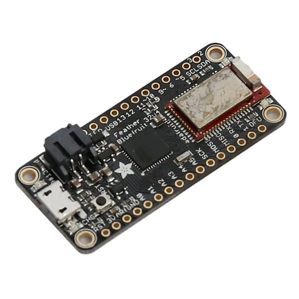
 ARM Microcontroller STM32F205RG Flash Code Recovery
ARM Microcontroller STM32F205RG Flash Code Recovery starts from crack mcu chip stm32f205rg protective system and then decode secured flash memory software from microprocessor stm32f205rg;
ARM Microcontroller STM32F205RG Flash Code Recovery starts from crack mcu chip stm32f205rg protective system and then decode secured flash memory software from microprocessor stm32f205rg;
The memory protection unit (MPU) is used to manage the CPU accesses to memory to prevent one task to accidentally corrupt the memory or resources used by any other active task. This memory area is organized into up to 8 protected areas that can in turn be divided up into 8 subareas. The protection area sizes are between 32 bytes and the whole 4 gigabytes of addressable memory.
La recuperación del código flash del microcontrolador ARM STM32F205RG comienza desde el sistema de protección crack mcu chip stm32f205rg y luego decodifica el software de memoria flash seguro del microprocesador stm32f205rg
The MPU is especially helpful for applications where some critical or certified code has to be protected against the misbehavior of other tasks. It is usually managed by an RTOS (real- time operating system). If a program accesses a memory location that is prohibited by the MPU, the RTOS can detect it and take action. In an RTOS environment, the kernel can dynamically update the MPU area setting, based on the process to be executed.
crack stm32f205rg mcu fuse bit and readout embedded firmware from microcontroller’s flash memory
The MPU is optional and can be bypassed for applications that do not need it. The STM32F20x devices embed a 128-bit wide Flash memory of 128 Kbytes, 256 Kbytes, 512 Kbytes, 768 Kbytes or 1 Mbyte available for storing programs and data. The devices also feature 512 bytes of OTP memory that can be used to store critical user data such as Ethernet MAC addresses or cryptographic keys.
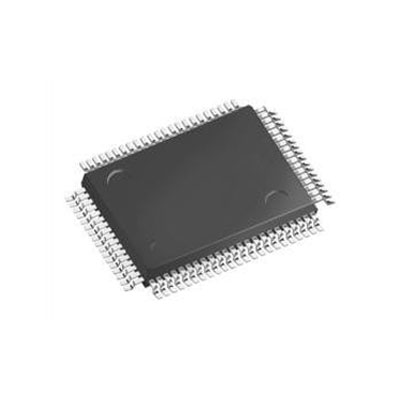
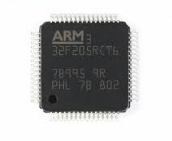
ARM STM32F205RC Microcontroller Flash Memory Heximal Recovery
ARM STM32F205RC Microcontroller Flash Memory Heximal Recovery starts from decrypting arm mcu stm32f205rc embedded memory program and then clone flash memory code to new mcu stm32f205rc;

ARM STM32F205RC Microcontroller Flash Memory Heximal Recovery starts from decrypting arm mcu stm32f205rc embedded memory program and then clone flash memory code to new mcu stm32f205rc;
The STM32F205xx and STM32F207xx devices operate in the –40 to +105 °C temperature range from a 1.8 V to 3.6 V power supply. On devices in WLCSP64+2 package, if IRROFF is set to VDD, the supply voltage can drop to 1.7 V when the device operates in the 0 to
70 °C temperature range using an external power supply supervisor (see Section 3.16).
A comprehensive set of power-saving modes enables the design of low-power applications.
STM32F205xx and STM32F207xx devices are offered in various packages, ranging from 64 to 176 pins. The set of included peripherals changes with the chosen device when recovering ic chip stm32f107rct6 code.These features make the STM32F205xx and STM32F207xx microcontroller family suitable for a wide range of applications:
- Motor drive and application control
- Medical equipment
- Industrial applications: PLC, inverters, circuit breakers
- Printers, and scanners
- Alarm systems, video intercom, and HVAC
- Home audio appliances
- For the LQFP100 package, only FSMC Bank1 or Bank2 are Bank1 can only support a multiplexed NOR/PSRAM memory using the NE1 Chip Select. Bank2 can only support a 16- or 8-bit NAND Flash memory using the NCE2 Chip Select. The interrupt line cannot be used since Port G is not available in this package.
- The SPI2 and SPI3 interfaces give the flexibility to work in an exclusive way in either the SPI mode or the I2S audio when breaking stm32f101c4 binary file;
- On devices in WLCSP64+2 package, if IRROFF is set to VDD, the supply voltage can drop to 7 V when the device operates in the 0 to 70 °C temperature range using an external power supply supervisor (see Section 3.16).
разблокировать микропроцессор STM32F205RCt6 и клонировать прошивку флэш-памяти на новый микроконтроллер STM32F205RCt6
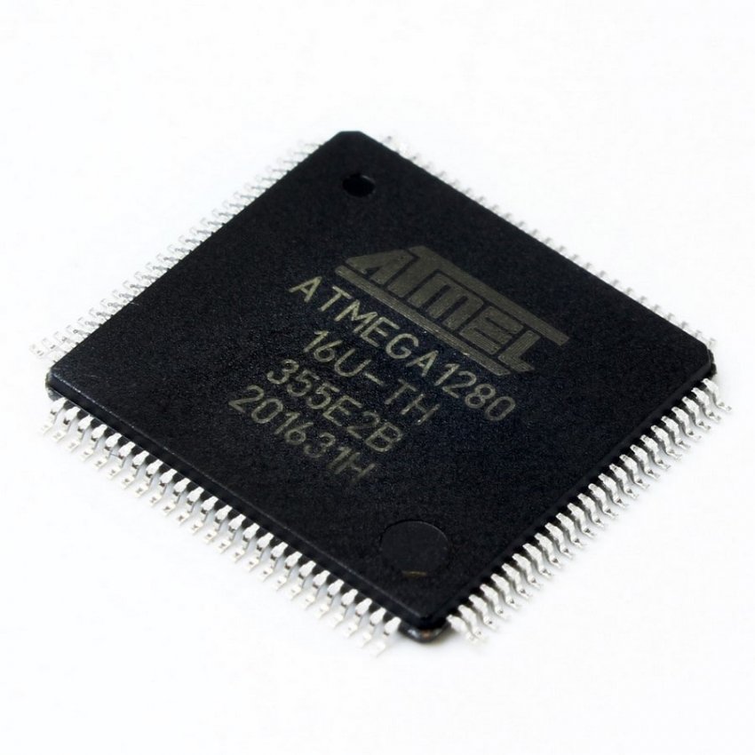
Microchip ATmega1280 Locked Microcontroller Heximal Restoration
Microchip ATmega1280 Locked Microcontroller Heximal Restoration needs to unlock mcu atmega1280 flash memory and then read out firmware program from atmega1280 flash and eeprom memory;
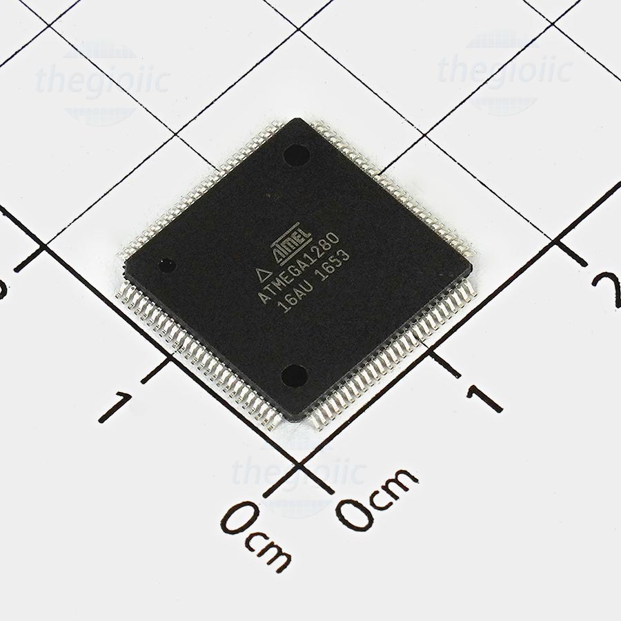
Microchip ATmega1280 Locked Microcontroller Heximal Restoration needs to unlock mcu atmega1280 flash memory and then read out firmware program from atmega1280 flash and eeprom memory
Port H is a 8-bit bi-directional I/O port with internal pull-up resistors (selected for each bit). The Port H output buf- fers have symmetrical drive characteristics with both high sink and source capability. As inputs, Port H pins that are externally pulled low will source current if the pull-up resistors are activated. The Port H pins are tri-stated when a reset condition becomes active, even if the clock is not running.
La restauración heximal del microcontrolador bloqueado ATmega1280 de Microchip necesita desbloquear la memoria flash mcu atmega1280 y luego leer el programa de firmware de la memoria flash atmega1280 y eeprom;
Port J is a 8-bit bi-directional I/O port with internal pull-up resistors (selected for each bit). The Port J output buffers have symmetrical drive characteristics with both high sink and source capability. As inputs, Port J pins that are externally pulled low will source current if the pull-up resistors are activated. The Port J pins are tri-stated when a reset condition becomes active, even if the clock is not running.
crack atmel atmega1280 mcu fuse bit and readout embedded firmware from microcontroller atmega1280 flash and eeprom memory
Port K is a 8-bit bi-directional I/O port with internal pull-up resistors (selected for each bit). The Port K output buffers have symmetrical drive characteristics with both high sink and source capability. As inputs, Port K pins that are externally pulled low will source current if the pull-up resistors are activated. The Port K pins are tri-stated when a reset condition becomes active, even if the clock is not running.
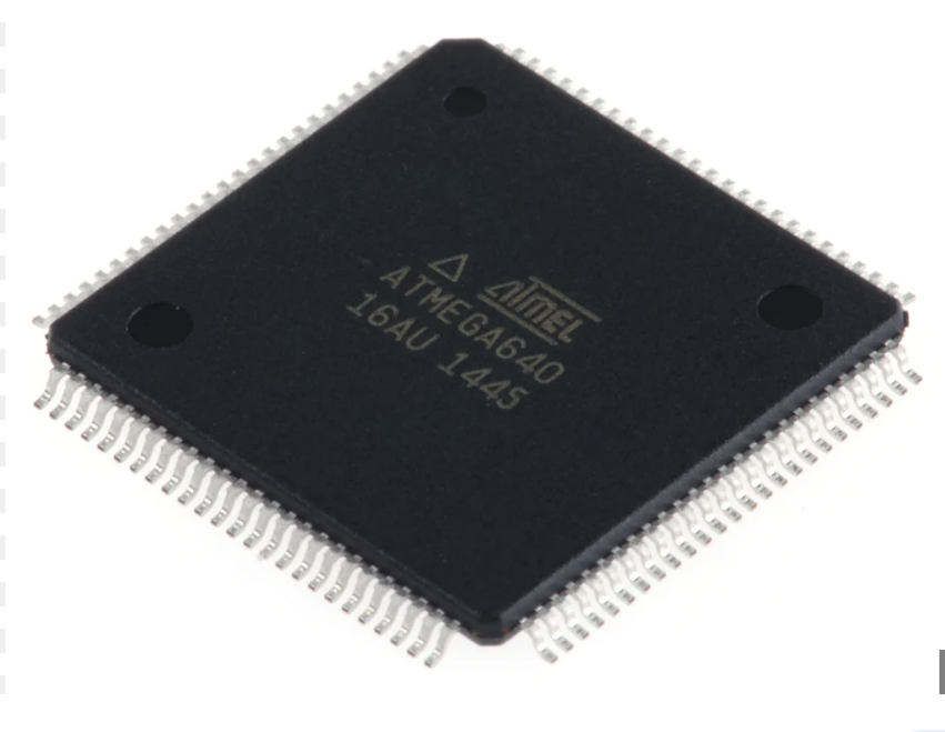
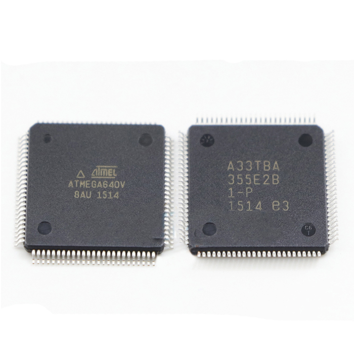
Secured Microchip ATMEGA640V MCU Flash Program Recovery
Secured Microchip ATMEGA640V MCU Flash Program Recovery needs to firstly crack mcu atmel atmega640v protective system and read atmega640v microcontroller flash memory content out from it;
Secured Microchip ATMEGA640V MCU Flash Program Recovery needs to firstly crack mcu atmel atmega640v protective system and read atmega640v microcontroller flash memory content out from it;
Port A is an 8-bit bi-directional I/O port with internal pull-up resistors (selected for each bit). The Port A output buf- fers have symmetrical drive characteristics with both high sink and source capability. As inputs, Port A pins that are externally pulled low will source current if the pull-up resistors are activated to recover atmega640v microcontroller flash firmware. The Port A pins are tri-stated when a reset condition becomes active, even if the clock is not running.
microchip seguro atmega640v mcu flash program recovery necesita primero descifrar el sistema de protección mcu atmel atmega640v y leer el contenido de la memoria flash del microcontrolador atmega640v.
Port B is an 8-bit bi-directional I/O port with internal pull-up resistors (selected for each bit). The Port B output buf- fers have symmetrical drive characteristics with both high sink and source capability. As inputs, Port B pins that are externally pulled low will source current if the pull-up resistors are activated. The Port B pins are tri-stated when a reset condition becomes active, even if the clock is not running.
recover atmega640v microprocessor flash memory content and copy firmware to new mcu chip atmega640v
Port C is an 8-bit bi-directional I/O port with internal pull-up resistors (selected for each bit). The Port C output buf- fers have symmetrical drive characteristics with both high sink and source capability after breaking ic chip atmega640v flash protection. As inputs, Port C pins that are externally pulled low will source current if the pull-up resistors are activated. The Port C pins are tri-stated when a reset condition becomes active, even if the clock is not running.
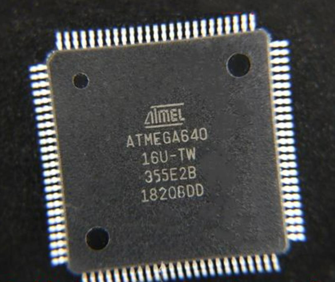
Protected ATMEGA640 MCU Chip Binary Restoration
Protected ATMEGA640 MCU Chip Binary Restoration is a process to unlock secured microcontroller atmega640 firmware from its flash memory and readout microprocessor atmega640 chipset flash and eeprom software data;
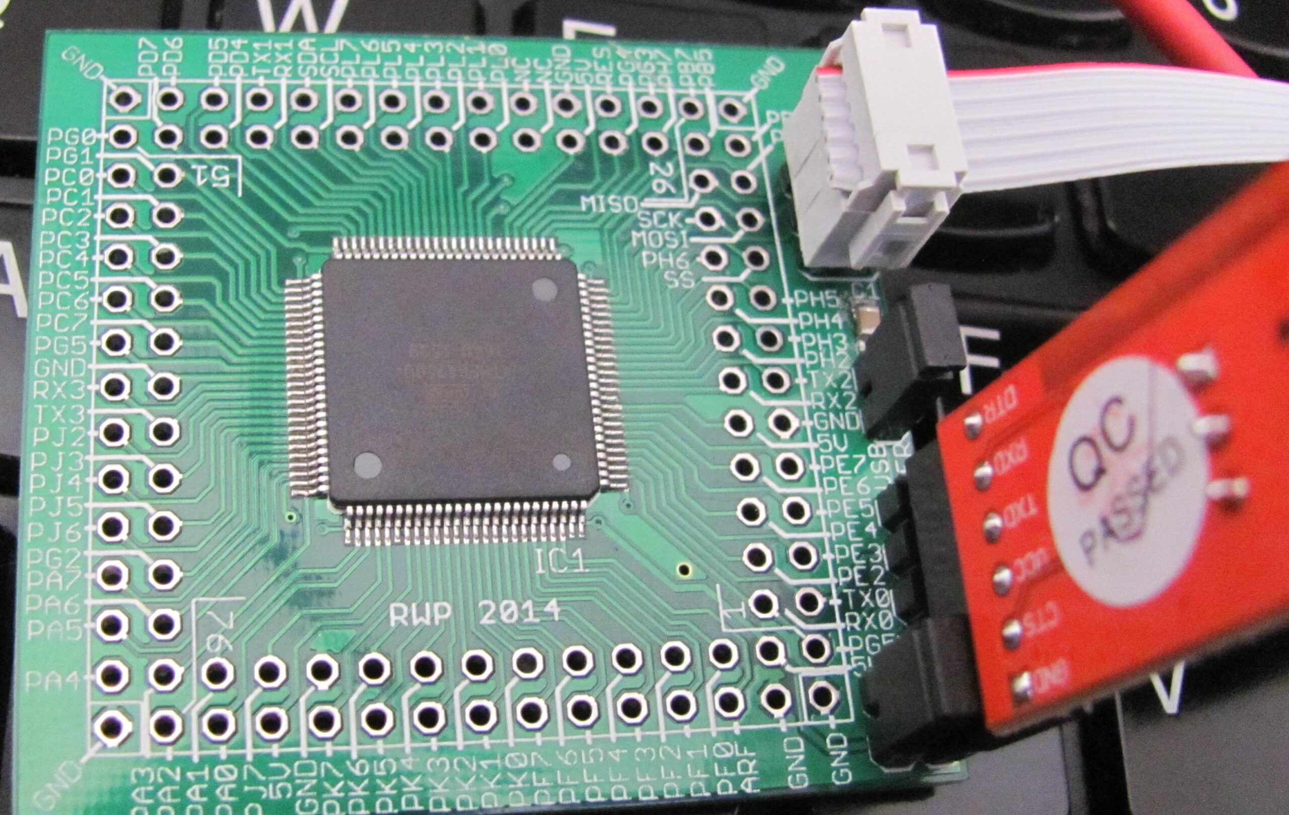
Protected ATMEGA640 MCU Chip Binary Restoration is a process to unlock secured microcontroller atmega640 firmware from its flash memory and readout microprocessor atmega640 chipset flash and eeprom software data;
The device is manufactured using the Microchip high-density nonvolatile memory technology. The On-chip ISP Flash allows the program memory to be reprogrammed in-system through an SPI serial interface, by a conventional nonvolatile memory programmer, or by an On-chip Boot program running on the AVR core.
La restauración binaria del chip ATMEGA640 MCU protegido es un proceso para desbloquear el firmware seguro del microcontrolador atmega640 de su memoria flash y leer los datos del software flash y eeprom del chipset atmega640 del microprocesador;
The boot program can use any interface to download the application program in the application Flash memory. Software in the Boot Flash section will continue to run while the Application Flash section is updated while reverse engineering atmega640 microcontroller fuse bit, providing true Read- While-Write operation. By combining an 8-bit RISC CPU with In-System Self-Programmable Flash on a monolithic chip, the ATmega640v is a powerful microcontroller that provides a highly flexible and cost effective solution to many embedded control applications.
crack atmega640 secured mcu fuse bit and readout embedded firmware from flash memory
The ATmega640v AVR is supported with a full suite of program and system development tools including: C compilers, macro assemblers, program debugger/simulators, in-circuit emulators, and evaluation kits. Each device in the ATmega640v family differs only in memory size and number of pins to recover mcu chip atmega640 heximal from flash memory. Table 2-1 summarizes the different configurations for the six devices.
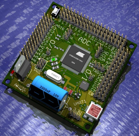
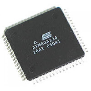
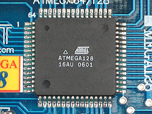
Copy AVR Microcontroller ATMEGA128 Flash Heximal
Copy AVR Microcontroller ATMEGA128 Flash Heximal needs to unlock avr secured mcu atmega128 protection, the un-encrypted avr microprocessor atmega128 flash memory binary will be extracted;
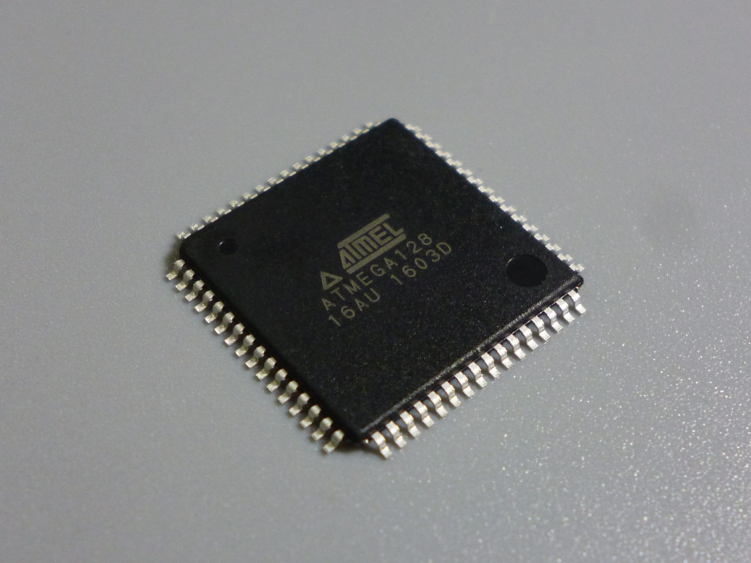
Copy AVR Microcontroller ATMEGA128 Flash Heximal needs to unlock avr secured mcu atmega128 protection, the un-encrypted avr microprocessor atmega128 flash memory binary will be extracted
The Power-on Reset will not work unless the supply voltage has been below VPOT (falling), VBOT may be below nominal minimum operating voltage for some devices. For devices where this is the case, the device is tested down to VCC = VBOT during the production test to break avr atmega128 mcu fuse bit and readout program. This guarantees that a Brown-out Reset will occur before VCC drops to a voltage where correct operation of the microcontroller is no longer guaranteed. The test is performed using BOD-LEVEL = 1 for ATmega8L and BODLEVEL = 0 for ATmega8. BODLEVEL = 1 is not applicable for ATmega128;
copia AVR microcontrolador ATMEGA128 flash heximal necesita para desbloquear avr asegurado mcu atmega128 protección, el no cifrado avr microprocesador atmega128 memoria flash binario será extraído;
A Power-on Reset (POR) pulse is generated by an On-chip detection circuit. The detection level is defined in Table 15 on page 38. The POR is activated whenever VCC is below the detection level. The POR circuit can be used to trigger the Start-up Reset, as well as to detect a failure in supply voltage.
break atmega128 microprocessor flash memory protection and extract embedded firmware
A Power-on Reset (POR) circuit ensures that the device is reset from Power-on. Reaching the Power-on Reset threshold voltage invokes the delay counter when break atmega128 microcontroller firmware, which determines how long the device is kept in RESET after VCC rise. The RESET signal is activated again, without any delay, when VCC decreases below the detection level.
Secured AVR Microcontroller ATMEGA64L Binary Replication
Secured AVR Microcontroller ATMEGA64L Binary Replication will need to attack avr atmega64l encrypted mcu fuse bit then readout embedded firmware from atmega64l microprocessor flash memory;
Secured AVR Microcontroller ATMEGA64L Binary Replication will need to attack avr atmega64l encrypted mcu fuse bit then readout embedded firmware from atmega64l microprocessor flash memory
Idle mode enables the MCU to wake up from external triggered interrupts as well as internal ones like the Timer Overflow and USART Transmit Complete interrupts. If wake-up from the Analog Comparator interrupt is not required, the Analog Comparator can be powered down by setting the ACD bit in the Analog Comparator Control and Status Register – ACSR when break off secured microcontroller atmega64l flash memory. This will reduce power consumption in Idle mode. If the ADC is enabled, a conversion starts automati- cally when this mode is entered.
asegurado microcontrolador AVR ATMEGA64L replicación binaria tendrá que atacar avr atmega64l cifrado mcu fusible bit a continuación, leer el firmware embebido de la memoria flash del microprocesador atmega64l;
When the SM2..0 bits are written to 001, the SLEEP instruction makes the MCU enter ADC Noise Reduction mode, stopping the CPU but allowing the ADC, the external interrupts, the Two-wire Serial Interface address watch, Timer/Counter2 and the Watchdog to continue operating (if enabled). This sleep mode basically halts clkI/O, clkCPU, and clkFLASH, while allowing the other clocks to run.

crack avr mcu atmega64l chip flash memory and dump its heximal code out from flash memory
This improves the noise environment for the ADC, enabling higher resolution measurements. If the ADC is enabled, a conversion starts automatically when this mode is entered. Apart form the ADC Conversion Complete interrupt, only an External Reset, a Watchdog Reset, a Brown-out Reset, a Two-wire Serial Interface address match interrupt, a Timer/Counter2 interrupt, an SPM/EEPROM ready interrupt by copying atmega64l microprocessor flash memory code to new MCU avr chip, or an external level interrupt on INT0 or INT1, can wake up the MCU from ADC Noise Reduction mode.
AVR MCU ATMEGA64 Flash Firmware Cloning
AVR MCU ATMEGA64 Flash Firmware Cloning is a process to attack encrypted atmega64 chip flash memory and readout embedded firmware from atmega64 mcu;
AVR MCU ATMEGA64 Flash Firmware Cloning is a process to attack encrypted atmega64 chip flash memory and readout embedded firmware from atmega64 mcu
The Oscillator can operate in three different modes, each optimized for a specific frequency range. The operating mode is selected by the fuses CKSEL3..1. These options should only be used when not operating close to the maximum frequency of the device, and only if frequency stability at start-up is not important for the application to copy atmega64l chip eeprom memory content. These options are not suitable for crystals.
AVR MCU ATMEGA64 flash firmware clonación es un proceso para atacar cifrado atmega64 chip de memoria flash y lectura de firmware embebido de atmega64 mcu;
These options are intended for use with ceramic resonators and will ensure frequency stability at start-up. They can also be used with crystals when not operating close to the maximum frequency of the device, and if frequency stability at start-up is not important for the application.
reverse engineering avr atmega64 chip and extract flash program from atmega64 mcu fuse bit
To use a 32.768kHz watch crystal as the clock source for the device, the Low-frequency Crystal Oscillator must be selected by setting the CKSEL Fuses to “1001”. The crystal should be connected as shown in Figure 11 on page 27. By programming the CKOPT Fuse, the user can enable internal capacitors on XTAL1 and XTAL2 to recover atmega64l mcu flash binary file, thereby removing the need for external capac- itors. The internal capacitors have a nominal value of 36pF.
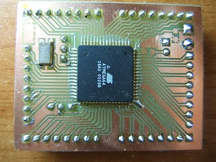
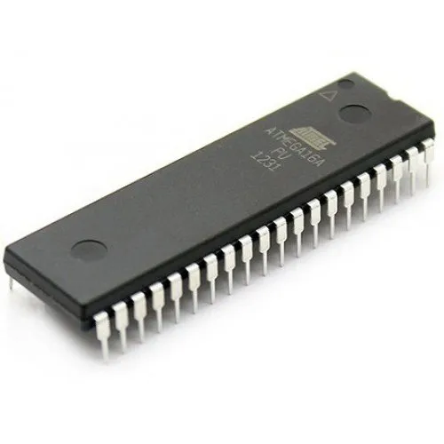
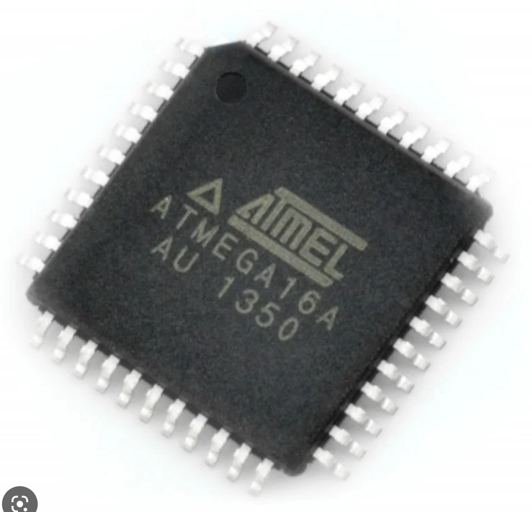
Secured Microcontroller ATmega16A Flash Code Extraction
Secured Microcontroller ATmega16A Flash Code Extraction needs to readout the program software from atmega16a locked mcu after unlock locked microprocessor atmega16a tamper resistance system;
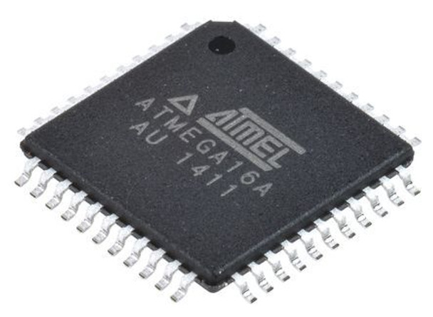
Secured Microcontroller ATmega16A Flash Code Extraction needs to readout the program software from atmega16a locked mcu after unlock locked microprocessor atmega16a tamper resistance system;
When entering Power-down sleep mode while an EEPROM write operation is active, the EEPROM write operation will continue, and will complete before the Write Access time has passed. However, when the write operation is completed, the Oscillator continues running, and as a consequence, the device does not enter Power-down entirely. It is therefore recommended to verify that the EEPROM write operation is completed before entering Power-down.
microcontrolador asegurado ATmega16A flash extracción de código necesita para leer el software del programa de atmega16a bloqueado mcu después de desbloquear microprocesador bloqueado atmega16a sistema de resistencia a la manipulación;
During periods of low VCC, the EEPROM data can be corrupted because the supply voltage is too low for the CPU and the EEPROM to operate properly. These issues are the same as for board level systems using EEPROM, and the same design solutions should be applied.
Защищенный микроконтроллер ATmega16A Извлечение флэш-кода необходимо для считывания программного обеспечения из заблокированного микроконтроллера atmega16a после разблокировки заблокированного микропроцессора atmega16a системы защиты от несанкционированного доступа;
An EEPROM data corruption can be caused by two situations when the voltage is too low. First, a regular write sequence to the EEPROM requires a minimum voltage to operate correctly. Sec- ond, the CPU itself can execute instructions incorrectly, if the supply voltage is too low to readout atmega16a ic chip locked code.
EEPROM data corruption can easily be avoided by following this design recommendation:
Keep the AVR RESET active (low) during periods of insufficient power supply voltage. This can be done by enabling the internal Brown-out Detector (BOD). If the detection level of the internal BOD does not match the needed detection level, an external low VCC Reset Protection circuit can be used. If a reset occurs while a write operation is in progress, the write operation will be completed provided that the power supply voltage is sufficient.
Locked MCU ATmega8L Flash Program Replication
Locked MCU ATmega8L Flash Program Replication needs to break off protective microcontroller atmega8l fuse bit, and then extract firmware from atmega8l microprocessor flash memory;
Locked MCU ATmega8L Flash Program Replication needs to break off protective microcontroller atmega8l fuse bit, and then extract firmware from atmega8l microprocessor flash memory;
Depending on the clock selection fuse settings, PB6 can be used as input to the inverting Oscil- lator amplifier and input to the internal clock operating circuit.
Depending on the clock selection fuse settings, PB7 can be used as output from the inverting Oscillator amplifier.
If the Internal Calibrated RC Oscillator is used as chip clock source, PB7..6 is used as TOSC2..1 input for the Asynchronous Timer/Counter2 if the AS2 bit in ASSR is set.
bloqueado MCU ATmega8L flash programa de replicación necesita para romper el microcontrolador protector atmega8l fusible bit, y luego extraer el firmware de la memoria flash del microprocesador atmega8l;
Port C is an 7-bit bi-directional I/O port with internal pull-up resistors (selected for each bit). The Port C output buffers have symmetrical drive characteristics with both high sink and source capability. As inputs, Port C pins that are externally pulled low will source current if the pull-up resistors are activated. The Port C pins are tri-stated when a reset condition becomes active, even if the clock is not running to restore atmega8l microcontroller flash data.
If the RSTDISBL Fuse is programmed, PC6 is used as an I/O pin. Note that the electrical char- acteristics of PC6 differ from those of the other pins of Port C.
hack atmega8l mcu tamper resistance and readout flash program from atmega8l microcontroller
If the RSTDISBL Fuse is unprogrammed, PC6 is used as a Reset input. A low level on this pin for longer than the minimum pulse length will generate a Reset, even if the clock is not running. The minimum pulse length is given in Table 15 on page 38. Shorter pulses are not guaranteed to generate a Reset when copying atmega8l microprocessor flash data.