Archive for August, 2012
 MCU Crack Security Solution
MCU Crack Security Solution was to place the EEPROM data storage chip next to the MCU inside the same plastic package. To attack such a MCU is not easy; a professional would decapsulate the sample and either microprobe the data or bond it into a separate test package.
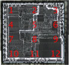
Both methods require equipment which cannot be afforded by a low-budget MCU Cracker. Such an MCU Cracker could try to use homemade microprobers (bonding pads on old chips are relatively large) or exploit a software bug to get access to the data.
Some microcontrollers do not have any special microcontroller hardware security protection at all. Their protection is based on obscurity of the proprietary programming algorithm. It might be the case that the read-back function was deliberately disguised, or replaced with a verify-only function.
Usually such MCUs do not offer very good protection and some examples are presented. In fact, the verify-only approach could be very powerful if implemented properly, as it is in some smartcards.
AVR Crack evolution in silicon chips
In the beginning there were almost no protection against avr crack of such devices except law and economics. For example, ROMs were made with low-cost mask technology and MCU Clone would involve either replacing them with EPROMs which are usually 3–10 times more expensive, or ordering Mask ROMs which would take time and require large capital investments. Another approach was used in game consoles where simple ASICs (Application-Specific Integrated Circuits) were widely used. Such ASICs were mainly carrying out I/O functions to replace tens of simple logic components, thus reducing the cost of the board and at the same time protecting against competitors who had to use larger and more expensive solutions. In fact these ASICs did not carry much security and their functionality could be understood in a few hours with a simple analysis of the signals using an oscilloscope or doing an exhaustive search over all possible combinations on their pins.
Open IC PIC16F73 Memory
Open IC PIC16F73 Memory include flash and eprom by MCU cracking technique, and extract code from microcontroller PIC16F73 in the format of heximal or binary;
The DRT operates on an internal RC oscillator. The processor is kept in RESET as long as the DRT is active. The DRT delay allows VDD to rise above VDD min., and for the oscillator to stabilize.
Oscillator circuits based on crystals or ceramic resonators require a certain time after power-up to establish a stable oscillation. The on-chip DRT keeps the device in a RESET condition for approximately 18 ms after MCLR has reached a logic high (VIHMCLR) level if recover mcu atmega164pa code.
Thus, programming GP3/MCLR/VPP as MCLR and using an external RC network connected to the MCLR input is not required in most cases, allowing for savings in cost-sensitive and/or space restricted applications, as well as allowing the use of the GP3/ MCLR/VPP pin as a general purpose input.
The Device Reset time delay will vary from chip to chip due to VDD, temperature, and process variation. See AC parameters for details.
The DRT will also be triggered upon a Watchdog Timer time-out. This is particularly important for applications using the WDT to wake from SLEEP mode automatically when reverse engineering IC atmega324pv code.
The Watchdog Timer (WDT) is a free running on-chip RC oscillator which does not require any external components. This RC oscillator is separate from the external RC oscillator of the GP5/OSC1/CLKIN pin and the internal 4 MHz oscillator.
That means that the WDT will run even if the main processor clock has been stopped, for example, by execution of a SLEEP instruction. During normal operation or SLEEP, a WDT reset or wake-up reset generates a device RESET.
The TO bit (STATUS<4>) will be cleared upon a Watchdog Timer reset. The WDT can be permanently disabled by programming the configuration bit WDTE as a ’0’. Refer to the PIC16F73 Programming. Specifications to determine how to access the configuration word.
Break Secured MCU PIC16F72 Data
Break Secured MCU PIC16F72 and extract Data of microcontroller PIC16F72 from flash memory and eeprom memory, make Microprocessor PIC16F72 cloning through the process;
The internal RC oscillator provides a fixed 4 MHz (nominal) system clock at VDD = 5V and 25°C, see “Electrical Specifications” section for information on variation over voltage and temperature.
For the PIC16F72, bits <7:2>, CAL5- CAL0 are used for calibration. Adjusting CAL5-0 from 000000 to 111111 yields a higher clock speed.
Note that bits 1 and 0 of OSCCAL are unimplemented and should be written as 0 when modifying OSCCAL for compatibility with future devices before reverse engineering Secured MCU atmega2560v firmware.
For the PIC16F72, the upper 4 bits of the register are used. Writing a larger value in this location yields a higher clock speed. This configuration bit when unprogrammed (left in the ‘1’ state) enables the external MCLR function. When programmed, the MCLR function is tied to the internal VDD, and the pin is assigned to be a GPIO.
See Figure 8-7. When pin GP3/MCLR/VPP is configured as MCLR, the internal pull-up is always on.The PIC12C5XX family incorporates on-chip Power On Reset (POR) circuitry which provides an internal chip reset for most power-up situations.
The on-chip POR circuit holds the chip in reset until VDD has reached a high enough level for proper operation. To take advantage of the internal POR, program the GP3/MCLR/VPP pin as MCLR and tie through a resistor to VDD or program the pin as GP3 before reverse engineering microcontroller atmega1281 data.
An internal weak pull-up resistor is implemented using a transistor. Refer to Table 11-1 for the pull-up resistor ranges. This will eliminate external RC components usually needed to create a Power-on Reset.
A maximum rise time for VDD is specified. See Electrical Specifications for details. When the device starts normal operation (exits the reset condition), device operating parameters (voltage, frequency, temperature, …) must be met to ensure operation. If these conditions are not met, the device must be held in reset until the operating parameters are met.
Reverse Engineering Schematic Diagram of Circuit Board
Schematic diagram is drawing formed by electrical simbol which can be applied to analyze the electronic circuit principle, it plays an indispensable part in the process of product adjustment, maintanence and modification. Reverse Engineering schematic diagram is the process base upon the physical circuit board sample or circuit board gerber file to obtain the result, which will facilitate the technology analysis and cooperate with the subsequent prototype adjustment and modification.
Reverse engineering schematic diagram start from the chip signal, designator of each lead’s signal are all given, at the same time, place emphasis on the corresponding relationship between package lead and physical sample lead, concentrate on the polarity of triode P/N and correctiveness of EBC, strict network verification must be made among the schematic diagram from reverse engineered and physical Printed circuit board sample. Ensure all the component’s designator, part number and network name are all clear and tracable, 100% correctiveness and readibility.
Besides, when reverse engineering schematic diagram from large size circuit card pattern, operator should understand the circuit layout relationship, and then divide the whole pattern into small blocks accompany with appropreaite signal indicator and explanation according to circuit functions, in stead of the traditional method like main bus as a whole plus net1 and net2 to express the connection relation. Which can effectively solve the problems of schematic diagram can’t be printed clearly.
Recover IC PIC16LF506 Data
Recover IC PIC16LF506 Data from embedded program memory and data memory, the embedded flash code can be readout from PIC16LF506 MCU after crack Microcontroller PIC16F506 protection;
Figure 8-5 shows a series resonant oscillator circuit. This circuit is also designed to use the fundamental frequency of the crystal. The inverter performs a 180-degree phase shift in a series resonant oscillator circuit.
The 330 Ω resistors provide the negative feedback to bias the inverters in their linear region. For timing insensitive applications, the RC device option offers additional cost savings if Recover mcu attiny45v program data.
The RC oscillator frequency is a function of the supply voltage, the resistor (Rext) and capacitor (Cext) values, and the operating temperature. In addition to this, the oscillator frequency will vary from unit to unit due to normal process parameter variation.
Furthermore, the difference in lead frame capacitance between package types will also affect the oscillation frequency, especially for low Cext values. The user also needs to take into account variation due to tolerance of external R and C components used after break IC attiny2313 code.
Figure 8-6 shows how the R/C combination is connected to the PIC12C5XX. For Rext values below 2.2 kΩ, the oscillator operation may become unstable, or stop completely.
For very high Rext values (e.g., 1 MΩ) the oscillator becomes sensitive to noise, humidity and leakage. Thus, we recommend keeping Rext between 3 kΩ and 100 kΩ.
Although the oscillator will operate with no external capacitor (Cext = 0 pF), we recommend using values above 20 pF for noise and stability reasons before Reverse engineering microcontroller attiny4313.
With no or small external capacitance, the oscillation frequency can vary dramatically due to changes in external capacitances, such as PCB trace capacitance or package lead frame capacitance.
The Electrical Specifications sections show RC frequency variation from part to part due to normal process variation. The variation is larger for larger R (since leakage current variation will affect RC frequency more for large R) and for smaller C (since variation of input capacitance will affect RC frequency more).
Decrypt Locked IC PIC16LF505 Program
Decrypt Locked IC PIC16LF505 and extract MCU PIC16LF505 Program from flash memory and data from eeprom memory, use invasive Microcontroller unlocking skill to disable its security fuse bit;
The PIC16LF505 can be operated in four different oscillator modes. The user can program two configuration bits (FOSC1:FOSC0) to select one of these four modes:
In XT or LP modes, a crystal or ceramic resonator is connected to the GP5/OSC1/CLKIN and GP4/OSC2 pins to establish oscillation (Figure 8-2). The PIC16LF505 oscillator design requires the use of a parallel cut crystal.
Use of a series cut crystal may give a frequency out of the crystal manufacturers specifications. When in XT or LP modes, the device can have an external clock source drive the GP5/OSC1/CLKIN pin (Figure 8-3) before break mcu atmega128pa firmware.
These values are for design guidance only. Since each resonator has its own characteristics, the user should consult the resonator manufacturer for appropriate values of external components.
These values are for design guidance only. Rs may be required to avoid overdriving crystals with low drive level specification. Since each crystal has its own characteristics, the user should consult the crystal manufacturer for appropriate values of external components.
Either a prepackaged oscillator or a simple oscillator circuit with TTL gates can be used as an external crystal oscillator circuit. Prepackaged oscillators provide a wide operating range and better stability.
A well-designed crystal oscillator will provide good performance with TTL gates. Two types of crystal oscillator circuits can be used: one with parallel resonance, or one with series resonance when break mcu atmega168a flash.
Figure 8-4 shows implementation of a parallel resonant oscillator circuit. The circuit is designed to use the fundamental frequency of the crystal. The 74AS04 inverter performs the 180-degree phase shift that a parallel oscillator requires.
The 4.7 kΩ resistor provides the negative feedback for stability. The 10 kΩ potentiometers bias the 74AS04 in the linear region. This circuit could be used for external oscillator designs.