Archive for October, 2012
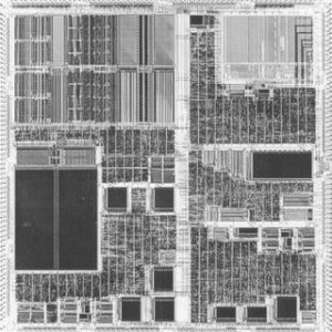
 Decode MCU ATmega2560V Program
Decode MCU ATmega2560V Program from encrypted flash memory is a process of Microcontroller firmware extraction, reset the status of microprocessor ATmega2560V by unlocking;
We can decode mcu ATMEGA2560V program, please view the mcu ATMEGA2560V features for your reference:
The Code memory array can be programmed using the serial SPI bus while RST is pulled to VCC. The serial interface consists of pins SCK, MOSI (input) and MISO (output) when copy mcu at89c55wd binary.
After RST is set high, the Programming Enable instruction needs to be executed first before program/erase operations can be executed. An auto-erase cycle is built into the self-timed programming operation (in the serial mode ONLY) and there is no need to first execute the Chip Erase instruction unless any of the lock bits have been programmed.
The Chip Erase operation turns the content of every memory location in the Code array into FFH. The Code memory array has an address space of 0000H to 2FFFH.
Either an external system clock is supplied at pin XTAL1 or a crystal needs to be connected across pins XTAL1 and XTAL2. The maximum serial clock (SCK) frequency should be less than 1/40 of the crystal frequency. With a 24 MHz oscillator clock, the maximum SCK frequency is 600 kHz. To program and verify the AT89S53 in the serial programming mode, the following sequence is recommended:
Power-up sequence: Apply power between VCC and GND pins. Set RST pin to “H”. If a crystal is not connected across pins XTAL1 and XTAL2, apply a 3 MHz to 24 MHz clock to XTAL1 pin and wait for at least 10 milliseconds if attack mcu atmega162 flash program.
Enable serial programming by sending the Programming Enable serial instruction to pin MOSI/P1.5. The frequency of the shift clock supplied at pin SCK/P1.7 needs to be less than the CPU clock at XTAL1 divided by 40..
The Code array is programmed one byte at a time by supplying the address and data together with the appropriate Write instruction.
The selected memory location is first automatically erased before new data is written. The write cycle is self-timed and typically takes less than 2.5 ms at 5V. Any memory location can be verified by using the Read instruction which returns the content at the selected address at serial output MISO/P1.6 before attack microcontroller w77e058a40dl flash program.
At the end of a programming session, RST can be set low to commence normal operation. Power-off sequence (if needed): Set XTAL1 to “L” (if a crystal is not used). Set RST to “L”. Turn VCC power off.
Break IC Flash
Break IC flash could be also applied to the device communication protocol in order to find any hidden functions embedded by the software developer for testing and upgrade purposes.
Break IC flash could be also applied to the device communication protocol in order to find any hidden functions embedded by the software developer for testing and upgrade purposes
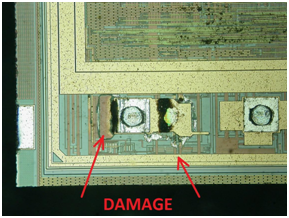
IC Chip manufacturers very often embed hardware test interfaces for postproduction testing of their semiconductor devices. If the security protection for these interfaces is not properly designed, the ic attacker can exploit it to get access to the on-chip memory. In smartcards such test interfaces are normally located outside the chip circuit and physically removed after the test operation, eliminating any possibility of use by outsiders.
Any security system, either software or hardware, could also have holes in its design and there is always a small chance that an ic cloner would eventually find one with brute force random testing. Careful design of the security protection, followed by proper evaluation, could help avoid many problems and make such MCU attack virtually impossible.
Read IC Program
Another possible brute force ic decryption when you are trying to Read IC Program, applicable to many semiconductor chips, is applying an external high voltage signal (normally twice the power supply) to the chip’s pins to find out whether one of them has any transaction like entering into a factory test or programming mode.
Another possible brute force ic decryption when you are trying to Read IC Program, applicable to many semiconductor chips, is applying an external high voltage signal (normally twice the power supply) to the chip’s pins to find out whether one of them has any transaction like entering into a factory test or programming mode
In fact, such pins can be easily found with a digital multimeter because they do not have a protection diode to the power supply line. Once sensitivity to a high voltage is found for any pin, MCU Cracker can try a systematic search on possible combinations of logic signals applied to other pins to figure out which of them are used for the test/programming mode and exploit this opportunity.
Clone IC Program
Clone IC Program from memory which include flash and eeprom memory, reset the status of Microcontroller Chip from locked to open one;
Clone IC Program from memory which include flash and eeprom memory,
One of the most effective ways of IC Clone is by Brute force MCU cracking, can be also applied to a hardware design implemented into an ASIC or a CPLD. In this case the IC attacker tries to apply all possible logic combinations to the input of the device while observing all its outputs. That kind of ic break could be also called black-box analysis because the ic decryption expert does not have to know anything about the design of the device under test.
He only tries to understand the function of the device by trying all possible combinations of signals. This approach works well only for relatively small logic devices. Another problem when extracting program from IC memory will face is that designs implemented in CPLDs or ASICs have flip-flops, so the output will probably be function of both the previous state and the input. But the search space can be significantly reduced if the signals are observed and analysed beforehand. For example, clock inputs, data buses and some control signals could be easily identified, significantly reducing the area of search.
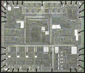
Decrypt Microprocessor ATmega1281 Eeprom
Decrypt Microprocessor ATmega1281 Eeprom and extract MCU ATmega1281 code from flash memory, prepare Microcontroller ATmega1281 unit clone by copy the firmware to new MCU unit;
Decrypt Microprocessor ATmega1281 Eeprom and extract MCU ATmega1281 code from flash memory, prepare Microcontroller ATmega1281 unit clone by copy the firmware to new MCU unit
The Instruction Set for Serial Programming follows a 3-byte protocol and is shown in the following table: Stresses beyond those listed under “Absolute Maximum Ratings” may cause permanent damage to the device.
This is a stress rating only and functional operation of the device at these or any other conditions beyond those indicated in the operational sections of this specification is not implied if breaking PIC16F716 heximal memory.
Exposure to absolute maximum rating conditions for extended periods may affect device reliability. Under operating conditions, load capacitance for Port 0, ALE/PROG, and PSEN = 100 pF; load capacitance for all other outputs = 80 pF.
Typical values contained in this datasheet are based on simulations and characterization of other AVR microcontrollers manufactured on the same process technology. Min and Max values will be available after the device is characterized. The ATmega1281 is a low-power CMOS 8-bit microcontroller based on the AVR enhanced RISC architecture.
By executing powerful instructions in a single clock cycle, the ATmega1281 achieves throughputs approaching 1 MIPS per MHz allowing the system designer to optimize power consumption versus processing speed.
The AVR core combines a rich instruction set with 32 general purpose working registers. All the 32 registers are directly connected to the Arithmetic Logic Unit (ALU), allowing two independent registers to be accessed in one single instruction executed in one clock cycle.
The resulting architecture is more code efficient while achieving throughputs up to ten times faster than conventional CISC microcontrollers.
Crack IC Flash
Crack IC Flash memory and extract the content inside flash memory, the program can be reprogramme to new MCU which can provide the same functions as originals;
Crack IC Flash memory and extract the content inside flash memory, the program can be reprogramme to new MCU which can provide the same functions as originals
‘Brute force’ has different meanings for cryptography and semiconductor hardware. A brute force MCU breaking would be defined as the methodical application of a large set of trials for a key to the system. This is usually done with a computer or an array of FPGAs delivering patterns at high speed and looking for success.
One example could be the password protection scheme used in microcontrollers, such as the Texas Instruments MSP430 family. The password itself is 32 bytes (256 bits) long which is more than enough to withstand direct brute force ic decode. But the password is allocated at the same memory addresses as the CPU interrupt vectors.
That, firstly, reduces the area of search as the vectors always point to even addresses within memory. Secondly, when the software gets updated, only a small part of the password is changed because most of the interrupt subroutines pointed to by the vectors are very likely to stay at the same addresses. As a result, if the ic breaker knows one of the previous passwords he could easily do a systematic search and find the correct password in a reasonable time.
Hack IC Program
Hack IC Program locked in the flash memory, remove the fuse bit of the Microcontroller by cracking technique, extract code from master MCU and reprogramme the file to new MCU;
Hack IC Program locked in the flash memory, remove the fuse bit of the Microcontroller by cracking technique, extract code from master MCU and reprogramme the file to new MCU
As one of the most effective method of IC crack, To prevent these ic program attack happen, the designer should carefully calculate the number of CPU cycles that take place when the password is compared and make sure they are the same for correct and incorrect passwords. For example, in the Motorola 68HC08 microcontrollers family the internal ROM bootloader allows access to the Flash memory only if the correct eight-byte password was entered first. To achieve that, extra NOP commands were added to the program making the processing time equal for both correct and incorrect bytes of the password. That gives good protection against timing mcu attacks. Some microcontrollers have an internal RC generator mode of operation in which the CPU running frequency depends upon the power supply voltage and the die temperature. This makes timing analysis more difficult as the mcu cracker has to stabilize the device temperature and reduce any fluctuations and noise on the power supply line. Some smartcards have an internally randomised clock signal to make measurements of the time delays useless for the ic break.
Attack IC Flash
Attack IC Flash memory by cut off the security fuse bit embedded among memories and center processor, read firmware out from flash, eeprom or ROM memory of Microcontroller, clone the heximal to new MCU;

Attack IC Flash memory by cut off the security fuse bit embedded among memories and center processor, read firmware out from flash, eeprom or ROM memory of Microcontroller, copy the heximal to new MCU
Timing ic attacks flash can be applied to microcontrollers whose security protection is based on passwords, or to access control systems that use cards or keys with fixed serial numbers, for example, Dallas iButton products. The common mistake in such systems is the way the serial number of the entered key is verified against the database. Very often the system checks each byte of the key against one entry in the database and stops as soon as an incorrect byte is found.
Then it switches to the next entry in the database until it reaches the end. So the ic cracker can easily measure the time between the input of the last key and the request for another key and figure out how many coincidences were found. With a relatively small number of attempts, he will be able to find one of the matching keys.
Extract IC Flash
Extract IC Flash memory content and copy code to new MCU memory which will provide the same functions as original Microcontroller;
Extract IC Flash memory content and copy code to new MCU memory which will provide the same functions as original Microcontroller
To conduct the ic flash extraction, the ic attacker one needs to collect a set of messages, together with their processing time, e.g. question-answer delay. Many cryptographic algorithms were found to be vulnerable to timing ic cracks. The main reason why this happens is in the software implementation of each algorithm.
That includes performance optimisation to bypass unnecessary branching and conditional operations, cache memory usage, non-fixed time processor instructions such as multiplication and division, and a wide variety of other causes. As a result performance characteristics typically depend on both the encryption key and the input data.
To prevent such MCU code restoration, the techniques used for blinding signatures can be used . The general idea is to prevent the attacker knowing the input to the modular exponentiation operation by mixing the input with a chosen random value.
Restore IC Program
Restore IC Program from its embedded flash memory and eeprom memory has to change the status of Microcontroller from encrypted to un-encrypted, then readout code from MCU memory with universal programmer;

Restore IC Program from its embedded flash memory and eeprom memory has to change the status of Microcontroller from encrypted to un-encrypted, then readout code from MCU memory with universal programmer
Semiconductor manufacturers offer valuable customers an easy way to increase the protection of their products: IC chips with custom marking on the packages instead of standard chip names. That gives the impression that the final product was designed using ASICs or full custom ICs.
‘Everyone knows’ that ASICs offer very good protection against different sorts of ic attacks and only well equipped and highly skilled ic crackers could succeed with br restore IC program from them. This may stop many potential mcu attackers fiddling with the product.
However, a determined mcu cracker could try an easy way to check whether this chip was actually an ASIC. The easy way is to note which pins are connected to power supply, ground, clock, reset, serial, and other interfaces, and to compare all this information with the database of suspect microcontrollers or other ICs.
This works very reliably, as each microcontroller family has its own characteristic pinout. Once similarities are found the suspected microcontroller could be verified by placing it into a programming device or universal programmer and trying to read it.