Archive for October, 2012
 Break Microcontroller ATmega1281V Firmware
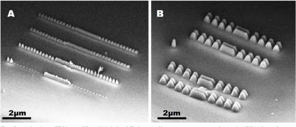
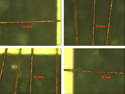
Break Microcontroller ATmega1281V embedded memory include flash and eeprom, extract firmware from MCU memory after reset the security fuse bit by focus ion beam technique, which is commonly method for microcontroller unlocking;
Break Microcontroller ATmega1281V embedded memory include flash and eeprom, extract firmware from MCU memory after reset the security fuse bit by focus ion beam technique, which is commonly method for microcontroller unlocking
The ATmega1281 provides the following features: 64K/128K/256K bytes of In-System Programmable Flash with Read-While-Write capabilities, 4K bytes EEPROM, 8K bytes SRAM, 54/86 general purpose I/O lines, 32 general purpose working registers when Microcontroller MC68HC11A0FN3 binary recovery.
Real Time Counter (RTC), six flexible Timer/Counters with compare modes and PWM, 4 USARTs, a byte oriented 2-wire Serial Interface, a 16-channel, 10-bit ADC with optional differential input stage with programmable gain, programmable Watchdog Timer with Internal Oscillator, an SPI serial port, IEEE std. 1149.1 compliant JTAG test interface, also used for accessing the On-chip Debug system and programming and six firmware selectable power saving modes if break Microcontroller LPC2132FBD64 firmware.
The Idle mode stops the CPU while allowing the SRAM, Timer/Counters, SPI port, and interrupt system to continue functioning. The Power-down mode saves the register contents but freezes the Oscillator, disabling all other chip functions until the next interrupt or Hardware Reset.
In Power-save mode, the asynchronous timer continues to run, allowing the user to maintain a timer base while the rest of the devMicrocontrollere is sleeping.
The ADC Noise Reduction mode stops the CPU and all I/O modules except Asynchronous Timer and ADC, to minimize switching noise during ADC conversions. In Standby mode, the Crystal/Resonator Oscillator is running while the rest of the devMicrocontrollere is sleeping.
This allows very fast start-up combined with low power consumption. In Extended Standby mode, both the main Oscillator and the Asynchronous Timer continue to run. The devMicrocontrollere is manufactured using Atmel’s high-density nonvolatile memory technology if break Microcontroller MC68HC11F1CFN3 heximal.
The On-chip ISP Flash allows the program memory to be reprogrammed in-system through an SPI serial interface, by a conventional nonvolatile memory programmer, or by an On-chip Boot program running on the AVR core. The boot program can use any interface to download the application.
Firmware in the Boot Flash section will continue to run while the Application Flash section is updated, providing true Read-While-Write operation. By combining an 8-bit RISC CPU with In-System Self-Program mable Flash on a Microcontroller chip, the Atmel ATmega1281 is a powerful Microcontroller that provides a highly flexible and cost effective solution to many embedded Microcontroller.
Copy IC Program
Copy IC Program from secured microcontroller flash program memory and eeprom data memory needs to crack Microcontroller firmware protective system, after that the firmware can be readout directly from Microprocessor memory cell;
Copy IC Program from secured microcontroller flash program memory and eeprom data memory needs to crack Microcontroller firmware protective system
When ic attacker invests a huge amount of money to reverse engineer a pay-TV access card. Then he disassembles the internal code from the card, learning everything that happens during authorisation and operation. Very likely he would be able to find vulnerabilities which give unlimited access to the subscription channels.
For example, by applying a power glitch at just the right moment to cause a malfunction of the CPU. Once he succeeded he could either offer the subscription service at a very competitive price, or sell equipment for counterfeiting the card to malicious people.
Obviously such an ic cracker needs to invest some capital to do this. But once he launches a pirate device on the market, it will be mcu attacked by others. This time the mcu crack will not be so expensive, because pirate devices are normally based on standard microcontrollers which have much lower security protection than pay-TV smartcards.
Very likely the device will be cracked in a few weeks, and the secondary attackers will flood the market with their clones. Fairly soon, the information on how to build pirate devices becomes available on the Internet and anyone can build pirate devices at almost no cost. So the pay-TV service provider loses millions of dollars; sometimes the original ic breaker is sued or prosecuted.
But because the lost profit was distributed among all the pirates and dishonest subscribers, the service provider hardly gets any money back. The only effect of such actions is to threaten the copyer community with punishment. In addition the service provider will have to spend a fortune on redesigning his access control system, choosing and developing software for the new smartcard, and distributing cards to the subscribers.
Decrypt Microprocessor ATmega2561 Dump
Decrypt Microprocessor ATmega2561 memory and extract dump from flash memory and eeprom memory, the content include program and data which will be presented in the format of binary or heximal;
Decrypt Microprocessor ATmega2561 memory and extract dump from flash memory and eeprom memory, the content include program and data which will be presented in the format of binary or heximal
The ATmega2561 AVR is supported with a full suite of program and system development tools including: C compilers, macro assemblers, program debugger/simulators, in-circuit emulators, and evaluation kits. Each device in the ATmega2561 family differs only in memory size and number of pins. Table 1 summarizes the different configurations for the six devices.
Port A is an 8-bit bi-directional I/O port with internal pull-up resistors (selected for each bit). The Port A output buffers have symmetrical drive characteristics with both high sink and source capability before decrypt copy microcontroller P87C51X2BBD binary.
As inputs, Port A pins that are externally pulled low will source current if the pull-up resistors are activated. The Port A pins are tri-stated when a reset condition becomes active, even if the clock is not running. Port B is an 8-bit bi-directional I/O port with internal pull-up resistors (selected for each bit).
The Port B output buffers have symmetrical drive characteristics with both high sink and source capability. As inputs, Port B pins that are externally pulled low will source current if the pull-up resistors are activated when recovery Microprocessor AT89C4051 heximal.
The Port B pins are tri-stated when a reset condition becomes active, even if the clock is not running. Port B has better driving capabilities than the other ports.
Port C is an 8-bit bi-directional I/O port with internal pull-up resistors (selected for each bit). The Port C output buffers have symmetrical drive characteristics with both high sink and source capability. As inputs, Port C pins that are externally pulled low will source current if the pull-up resistors are activated. The Port C pins are tri-stated when a reset condition becomes active, even if the clock is not running.
Port D is an 8-bit bi-directional I/O port with internal pull-up resistors (selected for each bit). The Port D output buffers have symmetrical drive characteristics with both high sink and source capability.
As inputs, Port D pins that are externally pulled low will source current if the pull-up resistors are activated. The Port D pins are tri-stated when a reset condition becomes active, even if the clock is not running.
Recover IC Program
Recover IC Program from secured MCU flash memory, the fuse bit of microcontroller will be cut by focus ion beam which one of the most commonly method for MCU crack and then copy code to new microprocesor;
Non-invasive ic attacks can be either passive or active. Passive ic cracks, also called side-channel IC code decoding, do not involve any interaction with the ic recover program device but, usually, observation of its signals and electromagnetic emissions. Examples of such mcu breaking are power analysis and timing attacks. Active ic cracks, like brute force and glitch attacks, involve playing with the signals applied to the device including the power supply line.
One example of a simple non-invasive recover ic program could be cloning a device based on SRAM FPGA as it is configured at a power-up. The ic program recover could easily connect to the JTAG interface wires used for configuring the chip and, with either an oscilloscope or a logic analyser, grab all the signals.
Then he can thoroughly analyse the waveforms and replay the commands in his own design. He could also slightly change the bitstream to disguise the fact of cloning as usually only half of the FPGA resources are used, leaving a room to fiddle with the configuration without harming device operation.
Also the JTAG interface itself gives some freedom in the sequence of the signals being applied so that the waveforms used to configure the pirate copy will look different from the original. In addition, the ic program recover could mix the row addresses during the upload, giving the impression of a completely different design.
Decrypt IC Program
Decrypt IC Program from locked microcontroller’s flash and eeprom memory, and then copy firmware out from MCU by programmer, rewrite the heximal to new MCU for cloning;
A non-invasive ic crack does not require any initial preparations of the device under test. The ic attacker can either tap the wires to the device, or plug it into a test circuit for the analysis. Once found, these mcu cracks could be easily scaled and their reproduction does not involve very much cost.
In addition, no tamper evidence is left after they are applied. Therefore they are considered to be the most serious threat to the hardware security of any device. At the same time it usually takes a lot of time and effort to find an ic program decryption on any particular device.
This often involves reverse engineering the device in the sense of either disassembling its software or understanding its hardware layout.
Recover Microprocessor ATmega2561V Code
Recover Microprocessor ATmega2561V Code is a process to extract program and data from MCU ATmega2561V memory after crack microcontroller tamper resistance system;
Port E is an 8-bit bi-directional I/O port with internal pull-up resistors (selected for each bit). The Port E output buffers have symmetrical drive characteristics with both high sink and source capability.
As inputs, Port E pins that are externally pulled low will source current if the pull-up resistors are activated when recover microprocessor code.
The Port E pins are tri-stated when a reset condition becomes active, even if the clock is not running. Port F serves as analog inputs to the A/D Converter. Port F also serves as an 8-bit bi-directional I/O port, if the A/D Converter is not used if attack microprocessor pic16c63a hex.
Port pins can provide internal pull-up resistors (selected for each bit). The Port F output buffers have symmetrical drive characteristics with both high sink and source capability. As inputs, Port F pins that are externally pulled low will source current if the pull-up resistors are activated.
The Port F pins are tri-stated when a reset condition becomes active, even if the clock is not running. If the JTAG interface is enabled, the pull-up resistors on pins PF7(TDI), PF5(TMS), and PF4(TCK) will be activated even if a reset occurs.
Port F also serves the functions of the JTAG interface. Port G is a 6-bit I/O port with internal pull-up resistors (selected for each bit). The Port G output buffers have symmetrical drive characteristics with both high sink and source capability when attack chip atmega8a binary.
As inputs, Port G pins that are externally pulled low will source current if the pull-up resistors are activated. The Port G pins are tri-stated when a reset condition becomes active, even if the clock is not running.
Port G also serves the functions of various special features of the ATmega2561 as listed on page 102.
Port H is a 8-bit bi-directional I/O port with internal pull-up resistors (selected for each bit). The Port H output buffers have symmetrical drive characteristics with both high sink and source capability. As inputs, Port H pins that are externally pulled low will source current if the pull-up resistors are activated. The Port H pins are tri-stated when a reset condition becomes active, even if the clock is not running before RECOVER MCU.
Port J is a 8-bit bi-directional I/O port with internal pull-up resistors (selected for each bit). The Port J output buffers have symmetrical drive characteristics with both high sink and source capability. As inputs, Port J pins that are externally pulled low will source current if the pull-up resistors are activated after recover microprocessor code.
The Port J pins are tri-stated when a reset condition becomes active, even if the clock is not running.
Break Microcontroller ATtiny48 Flash
Break Microcontroller ATtiny48 Flash memory and readout code from MCU, the file format of firmware will be binary or heximal;
Port K serves as analog inputs to the A/D Converter.
Port K is a 8-bit bi-directional I/O port with internal pull-up resistors (selected for each bit). The Port K output buffers have symmetrical drive characteristics with both high sink and source capability. As inputs, Port K pins that are externally pulled low will source current if the pull-up resistors are activated. The Port K pins are tri-stated when a reset condition becomes active, even if the clock is not running.
Port L is a 8-bit bi-directional I/O port with internal pull-up resistors (selected for each bit). The Port L output buffers have symmetrical drive characteristics with both high sink and source capability.
As inputs, Port L pins that are externally pulled low will source current if the pull-up resistors are activated. The Port L pins are tri-stated when a reset condition becomes active, even if the clock is not running.
Reset input. A low level on this pin for longer than the minimum pulse length will generate a reset, even if the clock is not running. The minimum pulse length is given in Table 23 on page 58. Shorter pulses are not guaranteed to generate a reset when break Microcontroller pic18f8722 flash.
Input to the inverting Oscillator amplifier and input to the internal clock operating circuit. Output from the inverting Oscillator amplifier. AVCC is the supply voltage pin for Port F and the A/D Converter if break Microcontroller flash.
It should be externally connected to VCC, even if the ADC is not used. If the ADC is used, it should be connected to VCC through a low-pass filter.
This is the analog reference pin for the A/D Converter. This documentation contains simple code examples that briefly show how to use various parts of the device. Be aware that not all C compiler vendors include bit definitions in the header files and interrupt handling in C is compiler dependent.
Please confirm with the C compiler documentation for more details. These code examples assume that the part specific header file is included before compilation. For I/O registers located in extended I/O map, “IN”, “OUT”, “SBIS”, “SBIC”, “CBI”, and “SBI” instructions must be replaced with instructions that allow access to extended I/O. Typically “LDS” and “STS” combined with “SBRS”, “SBRC”, “SBR”, and “CBR”.
Break IC Program
Break IC secured memory and extract program from MCU flash memory and eeprom memory, unlock microcontroller needs to figure out its internal scheme in order to locate the security fuse bit;
Fault injection IC program breaks done in a semi-invasive manner which can be used to modify the contents of SRAM and change the state of any individual transistor inside the chip. That gives almost unlimited capabilities to the ic breaker in getting control over the chip operation and abusing the protection mechanism.
Compared to non-invasive ic attacks, semi-invasive ic cracks are harder to implement as they require decapsulation of the chip. However, very much less expensive equipment is needed than for invasive mcu cracks. These ic program breaks can be performed in a reasonably short period of time. Also they are scalable to a certain extent, and the skills and knowledge required to perform them can be easily and quickly acquired. Some of these ic attacks, such as an exhaustive search for a security fuse, can be automated. If compared to invasive mcu cracks, the semi-invasive kind do not normally require precise positioning for success because they are normally applied to a whole transistor or even a group of transistors rather than to a single wire inside the chip.
IC Program Crack
Semi-invasive IC program crack are not entirely new. UV light has been used to disable security fuses in EPROM and OTP microcontrollers for many years.
Modern microcontrollers are less susceptible to this MCU cracking as they were designed to withstand it. More information on the evolution of defences against UV breaking in microcontrollers later. Advanced imaging techniques can be considered as semi-invasive as well.
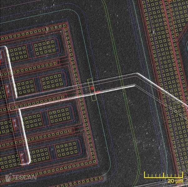
This includes various kinds of microscopy such as infrared, laser scanning and thermoimaging. Some of them can be applied from the rear side of the chip which is very useful for modern chips with multiple metal layer design. Some of these techniques allow observation of the state of each individual transistor inside the chip.
IC Program Attack
There is a large gap between previously discussed non-invasive ic program attack and invasive microcontroller unlocking, many mcu crackers fall into this gap, being not so expensive as classical penetrative invasive ic attacks but as easily repeatable as non-invasive program attacks.
Therefore we decided to define and introduce a new class of program attack called semi-invasive. Like invasive chip program attacks, they require depackaging the chip in order to get access to its surface. However, the passivation layer of the chip remains intact, as semi-invasive methods do not require depassivation or creating contacts to the internal lines. This is because microprobing is not used for this mcu program attack technology and thus such expensive tools as laser cutters and FIBs are not required.