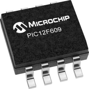
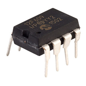
 Unlock Microchip PIC12F609 Processor Flash Content
Unlock Microchip PIC12F609 Processor Flash Content and extract heximal file to new Microcontroller pic12f609;

Desbloquee el contenido flash del procesador Microchip PIC12F609 y extraiga el archivo heximal al nuevo microcontrolador pic12f609;
This would allow an application to briefly wake-up, perform routine “housekeeping” tasks and return to Sleep before the device starts to operate from the primary oscillator.
User code can also check if the primary clock source is currently providing the system clocking by checking the status of the OSTS bit (OSCCON<3>). If the bit is set, the primary oscillator is providing the system clock. Otherwise, the internal oscillator block is providing the clock during wake-up from Reset or Sleep mode.
The Fail-Safe Clock Monitor (FSCM) allows the micro- controller to continue operation, in the event of an external oscillator failure, by automatically switching the system clock to the internal oscillator block by extracting pic12f617 microcontroller source code. The FSCM function is enabled by setting the Fail-Safe Clock Monitor Enable bit, FSCM (CONFIG1H<6>).

Odblokuj zawartość Flash procesora Microchip PIC12F609 i wyodrębnij plik szesnastkowy do nowego mikrokontrolera pic12f609
When FSCM is enabled, the INTRC oscillator runs at all times to monitor clocks to peripherals and provide an instant backup clock in the event of a clock failure. Clock monitoring (shown in Figure 19-3) is accom- plished by creating a sample clock signal, which is the INTRC output divided by 64 when breaking off the protection over pic16f627 mcu fuse bit. This allows ample time between FSCM sample clocks for a peripheral clock edge to occur. The peripheral system clock and the sample clock are presented as inputs to the Clock Monitor latch (CM). The CM is set on the falling edge of the system clock source, but cleared on the rising edge of the sample clock.