Posts Tagged ‘wiedererlangen Quellcode der MCU-Chip-Speichersoftware’
 Recover Microprocessor TMS320F2801PZA Secured Flash Binary
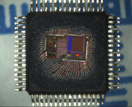
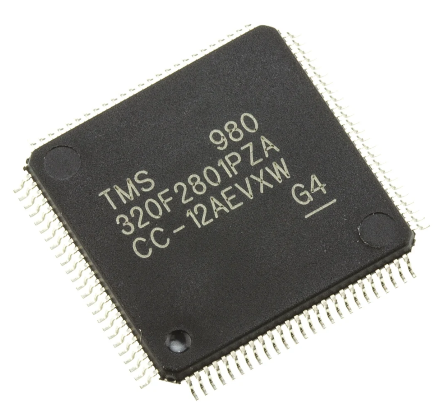
Recover Microprocessor TMS320F2801PZA Secured Flash Binary and clone flash memory file to new dsp microcontroller tms320f2801pza, the original memory program will be readout from tms320f2801pza processor;
The baseline IDD current (current when the core is executing a dummy loop with no peripherals enabled) is 40 mA, typical. To arrive at the IDD current for a given application, the current-drawn by the peripherals (enabled by that application) must be added to the baseline IDD current.
Following are other methods to reduce power consumption further:
The flash module may be powered down if code is run off SARAM. This results in a current reduction of 18 mA (typical) in the VDD rail and 13 mA (typical) in the VDDIO rail to attack tms320f28027 mcu archive file from its flash memory.
Savings in IDDIO may be realized by disabling the pullups on pins that assume an output function.
recuperar microprocesador TMS320F2801PZA asegurado binario flash y clonar archivo de memoria flash a nuevo microcontrolador dsp tms320f2801pza, el programa de memoria original será readout de procesador tms320f2801pza
To realize the lowest VDDA current consumption in a low-power mode, see the respective analog chapter of the TMS320F2803x Real-Time Microcontrollers Technical Reference Manual to ensure each module is powered down as well.
These values are based on a JEDEC defined 2S2P system (with the exception of the Theta JC [RΘJC] value, which is based on a JEDEC defined 1S0P system) and will change based on environment as well as application to . For more information, see these EIA/JEDEC standards:
JESD51-2, Integrated Circuits Thermal Test Method Environmental Conditions – Natural Convection (Still Air) by break ic tms320f28044 heximal from mcu;
JESD51-3, Low Effective Thermal Conductivity Test Board for Leaded Surface Mount Packages
JESD51-7, High Effective Thermal Conductivity Test Board for Leaded Surface Mount Packages
JESD51-9, Test Boards for Area Array Surface Mount Package Thermal Measurements
(2) lfm = linear feet per minute