Posts Tagged ‘Restaurando a memória flash ATmega32 do microcontrolador ATMEL AVR’
 ATMEL AVR Microcontroller ATmega32 Flash Memory Breaking
ATMEL AVR Microcontroller ATmega32 Flash Memory Breaking is a process to clone embedded code from atmega32 mcu flash memory, the firmware of flash memory of avr mcu atmega32 can be readout;
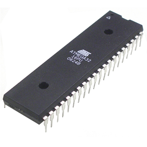
ATMEL AVR Microcontroller ATmega32 Flash Memory Breaking is a process to clone embedded code from atmega32 mcu flash memory, the firmware of flash memory of avr mcu atmega32 can be readout
The Register File is optimized for the AVR Enhanced RISC instruction set. In order to achieve the required performance and flexibility, the following input/output schemes are supported by the Register File:
- One 8-bit output operand and one 8-bit result input
- Two 8-bit output operands and one 8-bit result input
- Two 8-bit output operands and one 16-bit result input
- One 16-bit output operand and one 16-bit result input
Figure 3 shows the structure of the 32 general purpose working registers in the CPU.
Most of the instructions operating on the Register File have direct access to all registers, and most of them are single cycle instructions.
ATMEL AVR microcontrolador ATmega32 romper la memoria flash es un proceso para clonar código embebido de la memoria flash mcu atmega32, el firmware de la memoria flash de avr mcu atmega32 puede ser readout;
As shown in Figure 3, each register is also assigned a Data memory address, mapping them directly into the first 32 locations of the user Data Space. Although not being physically implemented as SRAM locations, this memory organization provides great flexibility in access of the registers to copy avr microcontroller atmega32 flash software, as the X-pointer, Y-pointer, and Z-pointer Registers can be set to index any register in the file.
The registers R26..R31 have some added functions to their general purpose usage. These reg- isters are 16-bit address pointers for indirect addressing of the Data Space. The three indirect address registers X, Y and Z are defined as described in Figure 4.
The Stack is mainly used for storing temporary data, for storing local variables and for storing return addresses after interrupts and subroutine calls. The Stack Pointer Register always points to the top of the Stack. Note that the Stack is implemented as growing from higher memory loca- tions to lower memory locations. This implies that a Stack PUSH command decreases the Stack Pointer.
crack avr atmel microprocessor atmega32 fuse bit and extract embedded code from atmega32 mcu flash memory
The Stack Pointer points to the data SRAM Stack area where the Subroutine and Interrupt Stacks are located. This Stack space in the data SRAM must be defined by the program before any subroutine calls are executed or interrupts are enabled. The Stack Pointer must be set to point above 0x60 by recovering atmega32 microprocessor flash memory content.
The Stack Pointer is decremented by one when data is pushed onto the Stack with the PUSH instruction, and it is decremented by two when the return address is pushed onto the Stack with subroutine call or interrupt. The Stack Pointer is incremented by one when data is popped from the Stack with the POP instruction, and it is incremented by two when address is popped from the Stack with return from subroutine RET or return from interrupt RETI.