 Reverse Engineering Microchip PIC18F4423 Memory
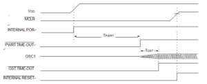
Reverse Engineering Microchip PIC18F4423 Memory can start from reseting the state of registers, knows the time-out sequence can help engineer better know the procedures of data stream flowing from one part to another:
On power-up, the time-out sequence is as follows:
1. The POR pulse clears.
2. PWRT time-out is invoked (if enabled).
3. The OST time-out is invoked. The oscillator starts at the beginning of this period.
4. PLL lock time-out (if using HSPLL mode).
The total time-out will vary based on oscillator configuration and the status of the PWRT by Attack MCU MSP430G2452IPW14R Heximal. all depict time-out sequences on power-up, with the Power-up Timer enabled and the device operating in HS Oscillator mode.
Reverse Engineering Microchip PIC18F4423 Memory
Figures 4-3 through 4-6 also apply to devices operating in XT or LP modes. For devices in RC mode and with the PWRT disabled, on the other hand, there will be no time-out at all.
Since the time-outs occur from the POR pulse, if MCLR is kept low long enough, all time-outs will expire. Bring- ing MCLR high will begin execution immediately (below Figure). This is useful for testing purposes or to synchronize more than one PIC18FXXXX device operating in parallel when Attack IC TMS320F28232PGFA Software.
Most registers are unaffected by a Reset. Their status is unknown on POR and unchanged by all other Resets. The other registers are forced to a “Reset state” depending on the type of Reset that occurred.
Most registers are not affected by a WDT wake-up, since this is viewed as the resumption of normal operation. Status bits from the RCON register, RI, TO, PD, POR and BOR, are set or cleared differently in different Reset situations when Crack MCU program, as indicated in Table 4-3. These bits are used in software to determine the nature of the Reset.