R8C R5F21324CNSP Microcontroller Flash Program Recovery
R8C R5F21324CNSP Microcontroller Flash Program Recovery will help engineer to restore embedded firmware inside flash memory of R5F21324CNSP, fuse bit of microprocessor R5F21324CNSP can be cracked;
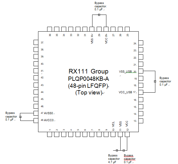
This MCU integrates an internal voltage-down circuit, which is used for lowering the power supply voltage in the internal MCU to adjust automatically to the optimum level. A 4.7-μF capacitor needs to be connected between this internal voltage-down power supply (VCL pin) and VSS pin.
R8C R5F21324CNSP microcontrolador de recuperação do programa flash ajudará o engenheiro a restaurar o firmware incorporado dentro da memória flash de R5F21324CNSP, bit de fusível do microprocessador R5F21324CNSP pode ser rachado;
Below Figure 1 to Figure 5.64 shows how to connect external capacitors. Place an external capacitor close to the pins especially when dumping renesas r5f212a7 protected MCU flash program. Do not apply the power supply voltage to the VCL pin. Insert a multilayer ceramic capacitor as a bypass capacitor between each pair of the power supply pins. Implement a bypass capacitor to the MCU power supply pins as close as possible.
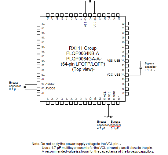
Use a 4.7-µF multilayer ceramic for the VCL pin and place it close to the pin. A recommended value is shown for the capacitance of the bypass capacitors
Use a recommended value of 0.1 μF as the capacitance of the capacitors. For the capacitors related to crystal oscillation, see section 9, Clock Generation Circuit in the User’s Manual: Hardware. For the capacitors related to analog modules, also see section 30, 12-Bit A/D Converter (S12ADb) in the User’s Manual: Hardware.