Archive for the ‘Break IC’ Category
 Extract IC Program
 October 2nd, 2012 |
  Author:
 Extract IC program execution has greater complexity, some of them can be done without expensive laboratory equipment.
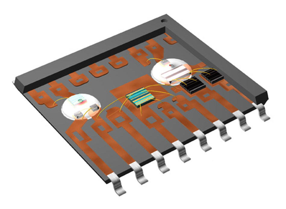
Low-budget MCU breakers are likely to get a cheap solution on the second-hand market for semiconductor test equipment. With patience and skill, it should not be too difficult to assemble all the required tools for under ten thousand pounds by buying a second-hand microscope and using self-designed micropositioners.
Invasive IC crackers start with the removal of the chip package. Once the chip is opened it is possible to perform probing or modifying microcontroller. The most important tool for invasive IC code extraction is a microprobing workstation. Its major component is a special optical microscope with a long working distance objective lens.
Micropositioners are installed on a stable platform around the chip test socket and allow the movement of probe arms, with submicron precision, over a chip surface. A probing needle with an elastic hair at the end is installed on each arm and allows electrical contact to on-chip bus lines without damaging them.
 Posted in Break IC |
  Tags: chip program extract, cpld program extract, dsp program extract, fpga program extract, mcu program extract, pld program extract, smartcard program extract |
  Comments Closed
Reverse Engineering IC Firmware
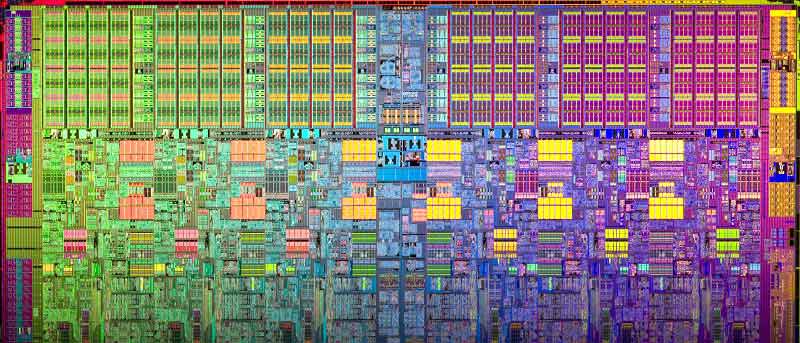
The next possible way of reverse engineering IC firmware from a device is playing around with its interface signals and access protocols. Also, if a security protocol is wrongly implemented, that leaves a hole for the ic reverse engineering firmware people to exploit.
Some microcontrollers and smartcards have a factory-test interface that provides access to on-chip memory and allows the manufacturer to test the device. If IC code extraction process can find a way of exploiting this interface, he can easily extract the information stored inside the chip.
Normally information on test circuits is kept secret by the manufacturer, but an MCU cracker can try applying different voltages and logic levels to the pins in the hope that it will put it into test mode. This sometimes works for microcontrollers but in smartcards such test circuitry is usually destroyed after use.
Also, embedded software developers sometimes implement functions that allow downloading from internal memory for test and update purposes. That must be done in a way that prevents any access to the code without proper authentication, or so that the code can be sent out in encrypted form only.
 Posted in Break IC |
Tags: cpld firmware reverse engineering, dsp firmware reverse engineering, fpga firmware reverse engineering, mcu firmware reverse engineering, pld firmware reverse engineering |
Comments Closed
Posted in Break IC |
Tags: cpld firmware reverse engineering, dsp firmware reverse engineering, fpga firmware reverse engineering, mcu firmware reverse engineering, pld firmware reverse engineering |
Comments Closed
Discover IC Code
The most widely used non-invasive discover IC code include playing around with the supply voltage and clock signal. Under-voltage and over-voltage microcontroller program reading could be used to disable protection circuit or force a processor to do the wrong operation.
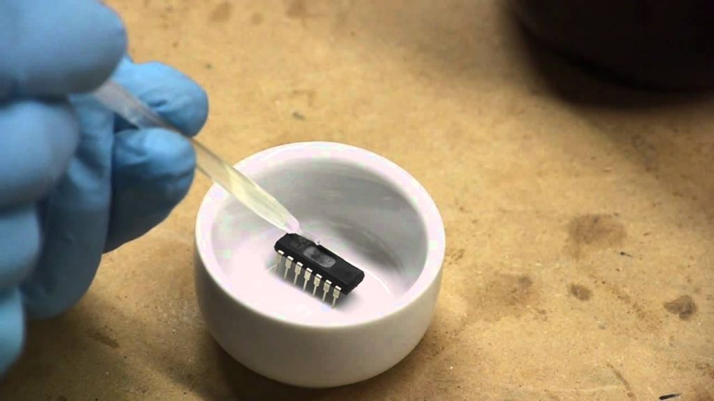
For these reasons, some security processors have a voltage detection circuit, but this circuit cannot react to fast transients when PIC16F57 heximal data decoding. Power and clock transients can also be used in some processors to affect the decoding and execution of individual instructions.
Another possible MCU cracking uses current analysis. We can measure with an analog-to-digital converter the fluctuations in the current consumed by the device. Drivers on the address and data bus often consist of up to a dozen parallel inverters per bit, each driving a large capacitive load.
They cause a significant power-supply short circuit during any transition. Changing a single bus line from ‘0’ to ‘1’ or vice versa can contribute in the order of 0.5–1mA to the drain current right after the clock edge. So a 12-bit ADC is sufficient to estimate the number of bus bits that change at anyone time. SRAM write operations often generate the strongest signals.
Posted in Break IC |
Tags: chip code discover, cpld code discover, dsp code discover, eeprom code discover, flash eeprom code discover, fpga code discover, fram code discover, mask rom code discover, mcu code discover, mram code discover, nvram code discover, otp eprom code discover, pld code discover, sram code discover, static ram code discover, uv eprom code discover |
Comments Closed
Discover Chip Firmware
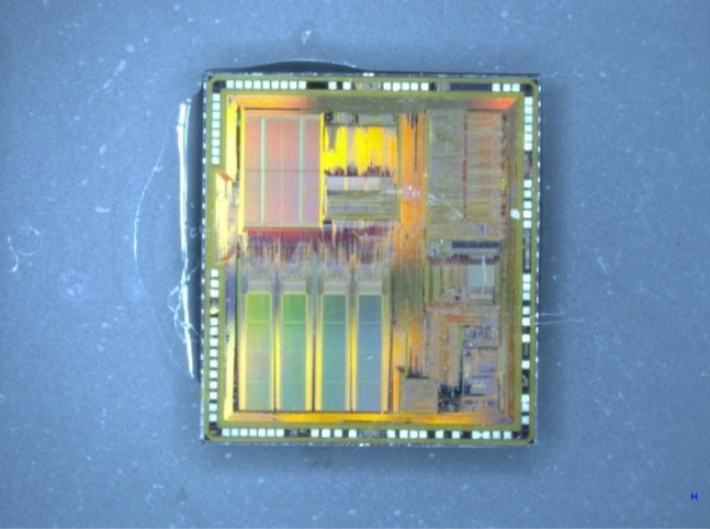
The next possible way of dicover chip firmware from a device is playing around with its interface signals and access protocols. Also, if a security protocol is wrongly implemented, that leaves a hole for the MCU cracker to exploit.
Some microcontrollers and smartcards have a factory-test interface that provides access to on-chip memory and allows the manufacturer to test the device. If an ic cracker can find a way of exploiting this interface, he can easily discover the firmware stored inside the chip. Normally information on test circuits is kept secret by the manufacturer, but an mcu cracker can try applying different voltages and logic levels to the pins in the hope that it will put it into test mode.
This sometimes works for microcontrollers but in smartcards such test circuitry is usually destroyed after use. Also, embedded software developers sometimes implement functions that allow reading from MCU internal memory for test and update purposes. That must be done in a way that prevents any access to the code without proper authentication, or so that the code can be sent out in encrypted form only.
 Posted in Break IC |
Tags: cpld firmware discover, dsp firmware discover, fpga firmware discover, ic firmware discover, mcu firmware discover, pld firmware discover |
Comments Closed
Posted in Break IC |
Tags: cpld firmware discover, dsp firmware discover, fpga firmware discover, ic firmware discover, mcu firmware discover, pld firmware discover |
Comments Closed
Clone IC Firmware
Clone IC Firmware from microcontroller’s embedded flash memory and eeprom memory, the IC code extraction normally bring with the MCU cracking tehnique;
Another possible IC program cloning method is using current analysis. We can measure with an analog-to-digital converter the fluctuations in the current consumed by the device. Drivers on the address and data bus often consist of up to a dozen parallel inverters per bit, each driving a large capacitive load.
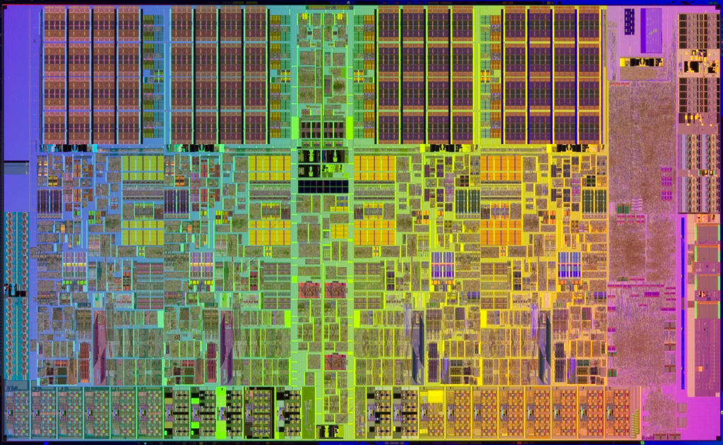
They cause a significant power-supply short circuit during any transition. Changing a single bus line from ‘0’ to ‘1’ or vice versa can contribute in the order of 0.5–1mA to the drain current right after the clock edge. So a 12-bit ADC is sufficient to estimate the number of bus bits that change at anyone time. SRAM write operations often generate the strongest signals.
Another possible threat to secure devices is data remanence. This is the capability of volatile memory to retain information for some time after power is disconnected. Static RAM storing the same key for a long period of time can reveal it on next power on.
Another possibility is to ‘freeze’ the memory by applying low temperature. In this case, static RAM can retain information for enough time to get access to the memory chip and read its contents. Data remanence can take place in non-volatile memories as well; the residual charge left on a floating gate transistor may be detected. For example, it could affect a threshold level or time-switching characteristics.
Posted in Break IC |
Tags: chip firmware clone, cpld firmware clone, dsp firmware clone, eeprom firmware clone, flash eeprom firmware clone, fpga firmware clone, fram firmware clone, mask rom firmware clone, mcu firmware clone, mram firmware clone, nvram firmware clone, otp eprom firmware clone, pld firmware clone, sram firmware clone, static ram firmware clone, uv eprom firmware clone |
Comments Closed
Break Microcontroller ATmega324PA Binary
Break Microcontroller ATmega324PA flash memory and extract MCU binary out from its embedded memory, the cloned ATmega324PA processor can be made through this process;
The device can operate its Timer/Counter2 from an external 32.768 kHz watch crystal or a external clock source. See Figure 22 on page 41 for crystal connection. Applying an external clock source to TOSC1 requires EXCLK in the ASSR Register written to logic one. See “Asynchronous operation of the Timer/Counter” on page 189 for further description on selecting external clock as input instead of a 32 kHz crystal.
The ATMEAG324PA has a system clock prescaler, and the system clock can be divided by setting the “Clock Prescale Register – CLKPR” on page 49. This feature can be used to decrease the system clock frequency and the power consumption when the requirement for processing power is low.
This can be used with all clock source options, and it will affect the clock frequency of the CPU and all synchronous peripherals. clkI/O, clkADC, clkCPU, and clkFLASH are divided by a factor after copy Microcontroller atmega8l hex.
When switching between prescaler settings, the System Clock Prescaler ensures that no glitches occurs in the clock system. It also ensures that no intermediate frequency is higher than neither the clock frequency corresponding to the previous setting, nor the clock frequency corresponding to the new setting.
The ripple counter that implements the prescaler runs at the frequency of the undivided clock, which may be faster than the CPU’s clock frequency. Hence, it is not possible to determine the state of the prescaler – even if it were readable, and the exact time it takes to switch from one clock division to the other cannot be exactly predicted. From the time the CLKPS values are written, it takes between T1 + T2 and T1 + 2 * T2 before the new clock frequency is active. In this interval, 2 active clock edges are produced. Here, T1 is the previous clock period, and T2 is the period corresponding to the new prescaler setting if recover Microcontroller stm32f107rct8 code.
To avoid unintentional changes of clock frequency, a special write procedure must be followed to change the CLKPS bits:
Write the Clock Prescaler Change Enable (CLKPCE) bit to one and all other bits in CLKPR to zero.
Within four cycles, write the desired value to CLKPS while writing a zero to CLKPCE.
Interrupts must be disabled when changing prescaler setting to make sure the write procedure is not interrupted.
The CLKPCE bit must be written to logic one to enable change of the CLKPS bits. The CLKPCE bit is only updated when the other bits in CLKPR are simultaneously written to zero. CLKPCE is cleared by hardware four cycles after it is written or when CLKPS bits are written. Rewriting the CLKPCE bit within this time-out period does neither extend the time-out period, nor clear the CLKPCE bit.
Decrypt IC Firmware
Decrypt IC firmware is one of the most widely used non-invasive methods include playing around with the supply voltage and clock signal. Under-voltage and over-voltage IC decryption could be used to disable protection circuit or force a processor to do the wrong operation.
For these reasons, some secured processors have a voltage detection circuit which has been used to against the MCU code reading, but this circuit cannot react to fast transients. Power and clock transients can also be used in some processors to affect the mcu program decoding and execution of individual instructions.
Another problem that affects hardware security is the fact that usually a whole family of chips from one manufacturer has the same implementation of the security protection. It means that once an attacker finds a way to overcome the security in one device, very likely he would be able to break another. Manufacturers do change the security protection from time to time, but again that affects a wide range of products simultaneously.
Nowadays attackers are very clever. They do not believe in what the manufacturers claim about the security of their products. They are constantly looking for new and low-cost attack methods, and they never give up. As a result there is a permanent battle between the manufacturers who are trying to improve the security of their products and the attackers who are constantly breaking these products.
There is no real change in this process within the last decade – only temporary shifts of the front line from time to time. For sure modern smartcards are extremely secure, but attackers are not idle and sometimes are very successful. That forces the developers to update their products quite often.
Posted in Break IC |
Tags: cpld firmware decrypt, dsp firmware decrypt, eeprom ic firmware decrypt, flash eeprom ic firmware decrypt, fpga firmware decrypt, fram ic firmware decrypt, mask rom ic firmware decrypt, mcu firmware decrypt, mram ic firmware decrypt, nvram ic firmware decrypt, otp eprom ic firmware decrypt, pld firmware decrypt, sram ic firmware decrypt, static ram ic firmware decrypt, uv eprom ic firmware decrypt |
Comments Closed
Break IC ATmega644 Eeprom
Break IC ATmega644 Eeprom can reset the microcontroller atmega644 fuse bit by MCU unlocking skill, and extract firmware of MCU ATmega644 memory;
These bits define the division factor between the selected clock source and the internal system clock. These bits can be written run-time to vary the clock frequency to suit the application requirements. As the divider divides the master clock input to the IC, the speed of all synchronous peripherals is reduced when a division factor is used.
The division factors are given in Table 20. The CKDIV8 Fuse determines the initial value of the CLKPS bits. If CKDIV8 is uneeprommed, the CLKPS bits will be reset to “0000”. If CKDIV8 is eeprommed, CLKPS bits are reset to “0011”, giving a division factor of 8 at start up. This feature should be used if the selected clock source has a higher frequency than the maximum frequency of the device at the present operating conditions. Note that any value can be written to the CLKPS bits regardless of the CKDIV8 Fuse setting.
The Application software must ensure that a sufficient division factor is chosen if the selected clock source has a higher frequency than the maximum frequency of the device at the present operating conditions before break IC eeprom after attack microcontroller st62t15c6 firmware.
The device is shipped with the CKDIV8 Fuse eeprommed. Sleep modes enable the application to shut down unused modules in the IC, thereby saving power. The AVR provides various sleep modes allowing the user to tailor the power consumption to the application’s requirements.
To enter any of the five sleep modes, the SE bit in SMCR must be written to logic one and a SLEEP instruction must be executed. The SM2, SM1, and SM0 bits in the SMCR Register select which sleep mode (Idle, ADC Noise Reduction, Power-down, Power-save, or Standby) will be activated by the SLEEP instruction.
See Table 21 for a summary. If an enabled interrupt occurs while the IC is in a sleep mode, the IC wakes The IC is then halted for four cycles in addition to the start-up time, executes the interrupt routine, and resumes execution from the instruction following SLEEP. The contents of the Register File and SRAM are unaltered when the device wakes up from sleep. If a reset occurs during sleep mode, the IC wakes up and executes from the Reset Vector.
Figure 21 on page 39 presents the different clock systems in the ATmega644, and their distribution. The figure is helpful in selecting an appropriate sleep mode.
The SE bit must be written to logic one to make the IC enter the sleep mode when the SLEEP instruction is executed. To avoid the IC entering the sleep mode unless it is the eeprommer’s purpose, it is recommended to write the Sleep Enable (SE) bit to one just before the execution of the SLEEP instruction and to clear it immediately after waking up before BREAK IC.
Hack IC firmware
Hack IC firmware can be used for different purposes depending on the goal. Sometimes copying a profitable on-the-market product can give easy money. Larger manufacturers could consider stealing intellectual property (IP) from the device and mixing it with their own IP to disguise the theft.
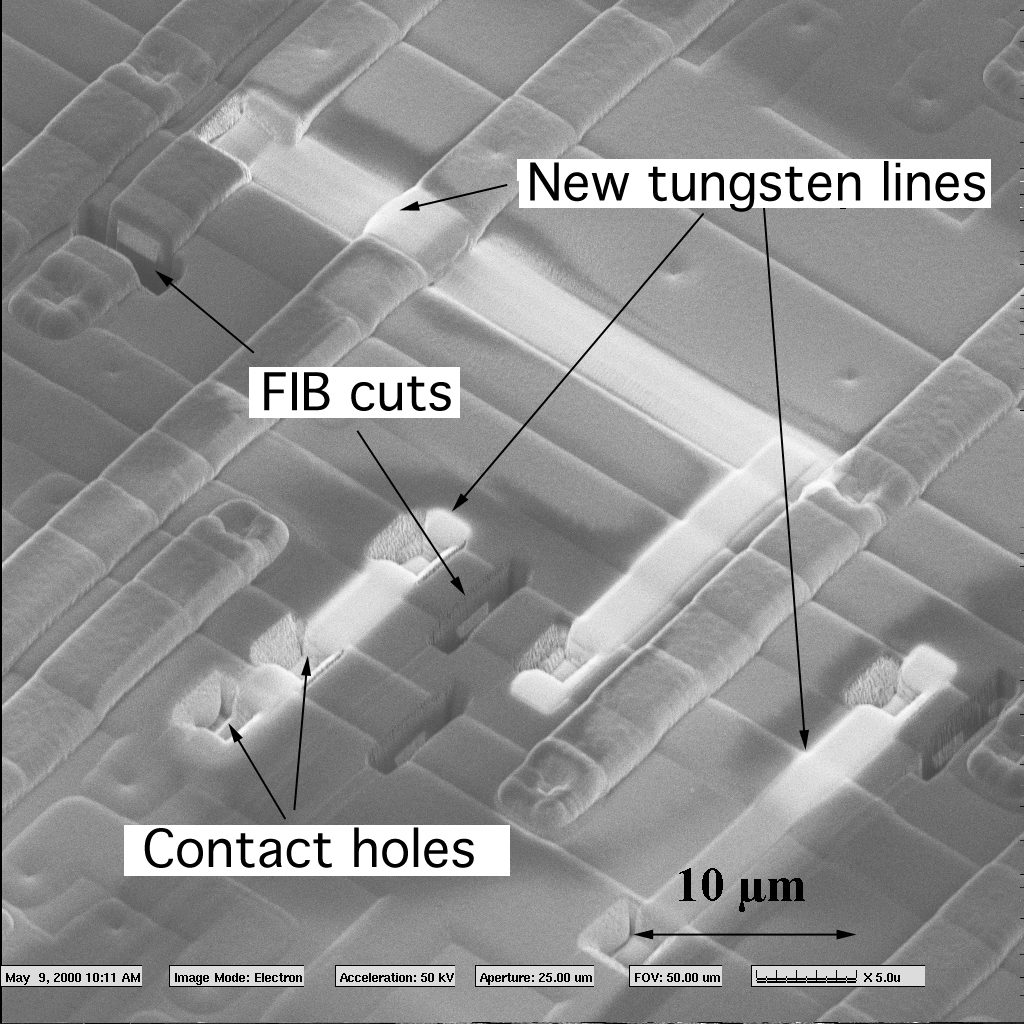
Others could try to steal secrets from the device either to produce a competitive product or to steal service. Product designers should first think about the possible motives for cracking microcontroller memory their devices and then concentrate on the protection mechanisms. The following MCU IC processsor Hacking scenarios should be considered during the system design.
Failure analysis involves testing and debugging silicon chips after fabrication. Very often the chip does not function in the required way, so the manufacturer wants to investigate the problem and fix it in the next revision of the die. When a new technological process or memory type is being developed, failure analysis techniques are used to measure all the parameters and make necessary alterations in further designs. Obviously such tools should provide the ability to observe signals at any point of the chip and, if necessary, make modifications to the silicon design. From the attacker’s point of view, a perfect failure analysis tool gives the ultimate
capability to circumvent security protection. It allows connection to any point on the chip die, and lets him disable the security protection by modifying the security circuit. Fortunately, with constant technological progress resulting in a significant reduction of the transistor feature
sizes, failure analysis becomes more and more complicated and expensive. It also forces the attackers to be more and more knowledgeable and experienced. Of course, not all failure analysis techniques are useful for breaking the security of chips. For example, an attacker is not interested in cross sectioning the chip, transistor sizes, thickness of the gate oxide or metallization.
Posted in Break IC |
Tags: cpld firmware hack, dsp firmware hack, eeprom firmware hack, flash eeprom firmware hack, fpga firmware hack, fram firmware hack, mask rom firmware hack, mcu firmware hack, mram firmware hack, nvram firmware hack, otp eprom firmware hack, pld firmware hack, sram firmware hack, static ram firmware hack, uv eprom firmware hack |
Comments Closed
Recover MCU IC Firmware
Recover MCU IC firmware can be reversible when the device can be put back into the initial state, or irreversible with permanent changes done to the device. For example, power analysis and microprobing could make ic firmware recovery a result without harming the device itself.
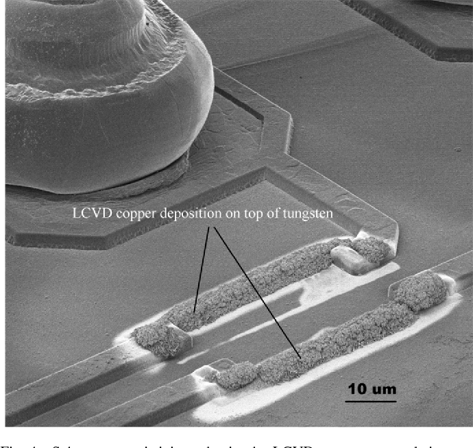
Certainly microprobing will leave tamper evidence but usually that does not affect further device operation. On the contrary, fault injection and UV light MCU code reading could very likely put the device into the state where the internal registers or memory contents are changed and cannot be recovered.
In addition, UV light microcontroller unlocking leave tamper evidence as they require direct access to the chip surface.
The first operation which is crucial for any invasive or semi-invasive attack is decapsulation of the chip sample to get access to the die surface. There are different techniques for doing this [66] and the most widely known and reliable method involves using hot fuming nitric acid to dissolve the plastic package material. A detailed explanation of this method is given in Chapter 5. Modern chips have multiple metal layers and in order to investigate and analyse the structure of the chip, the attacker must expose each layer, photograph it under a microscope and then combine all the photos together to get a complete picture. Then he could trace the signals from one transistor to another and simulate the whole chip. This process is called microcontroller reverse engineering and a basic overview of it is given in Chapter 5. For many years microprobing technology was used to observe the signals inside the chip during operation. This is a basic and simple way of extracting the information from semiconductor chips.
Posted in Break IC |
Tags: cpld firmware recovery, dsp firmware recovery, eeprom firmware recovery, eprom firmware recovery, flash eeprom firmware recovery, fpga firmware recovery, fram firmware recovery, mask rom firmware recovery, mcu firmware recovery, mram firmware recovery, pld firmware recovery, sram firmware recovery, static ram firmware recovery, uv eprom firmware recovery |
Comments Closed