Archive for the ‘Break IC’ Category
 PIC16F84A Microcontroller Chip Attack
 April 8th, 2013 |
  Author:
 PIC16F84A Microcontroller Chip Attack
It is not always necessary for the power glitches to be outside the specified power supply voltage range. For example, in the same PIC16F84A microcontroller the protection mechanism can be defeated by applying a mere 50 mV glitch after the chip erase operation has started which will cause the failure of PIC16F84A Microcontroller Chip Attack. That causes termination of the program memory erase operation but not the fuse erase.
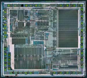
PIC16F84A Microcontroller Chip Attack
All the above examples of glitch attacks show how powerful such attacks can be unless special countermeasures are implemented. These could be voltage and clock monitor circuits which reset the CPU if the voltage or clock frequency go out of range. Clock-monitoring circuits are normally used in smartcards but very few microcontrollers have them.
Break Microprocessor W78E052 Locked Program
In the process of Break Microprocessor W78E052 Locked Program, first of all we should have a general understanding about Microprocessor W78E052.
The W78E052 is an 8-bit microcontroller which has an in-system programmable MTP-ROM for firmware updating. The instruction set of the W78E62B is fully compatible with the standard 8052. The W78E052 contains a 64K bytes of main MTP-ROM and a 4K bytes of auxiliary MTP-ROM which allows the contents of the 64KB main MTP-ROM to be updated by the loader program located at the 4KB auxiliary MTP-ROM;
512 bytes of on-chip RAM; four 8-bit bi-directional and bit-addressable I/O ports; an additional 4-bit port P4; three 16-bit timer/counters; a serial port. These peripherals are supported by a eight sources two-level interrupt capability.
To facilitate programming and verification, the MTP-ROM inside the W78E052 allows the program memory to be programmed and read electronically after Break Microprocessor W78E052 Locked Program. Once the code is confirmed, the user can protect the code for security.
The W78E052 microcontroller has two power reduction modes, idle mode and power-down mode, both of which are software selectable. The idle mode turns off the processor clock but allows for continued peripheral operation.
The power-down mode stops the crystal oscillator for minimum power consumption. The external clock can be stopped at any time and in any state without affecting the processor.
Fully static design 8-bit CMOS microcontroller up to 40
64K bytes of in-system programmable MTP-ROM for Application Program (APROM).
4K bytes of auxiliary MTP-ROM for Loader Program (LDROM).
Low standby current at full supply before Break Microprocessor W78E052 Locked Program
512 bytes of on-chip RAM. (including 256 bytes of AUX-RAM, software selectable)
64K bytes program memory address space and 64K bytes data memory address
Four 8-bit bi-directional
One 4-bit multipurpose programmable
Build-in 74373 and 74244 logical functions on Port 2.(software programmable)
Three 16-bit timer/counters
One full duplex serial port
Eight-sources, two-level interrupt capability
Built-in power management
Code protection
Port 4, SFR P4 at address D8H, is a 4-bit multipurpose programmable I/O port. Each bit can be configured individually by software. The Port 4 has four different operation mode:
In mode 0, P4.0-P4.3 is a bi-directional I/O port which is same as port 1. P4.2 and P4.3 also serve as external interrupt INT3 and INT2 if enabled.
In mode 1, P4.0-P4.3 are read data strobe signals which are synchronized with RD signal at specified addresses. These signals can be used as chip-select signals for external peripherals.
Extract PIC16F84 MCU Firmware
Extract PIC16F84 MCU Firmware from Microcontroller PIC16F84 flash and eeprom memory, reset the microprocessor status to unlocked one by crack MCU fuse bit and copy MCU’s code to new one;
Another example is an old PIC16F84 microcontroller from Microchip. The chip erase operation removes the security protection but at the same time erases the contents of program and data memories on the chip. The hardware design of the security protection circuit is made such that the memory is always erased before the security fuse is reset to the initial state.
However it was found that if during the chip erase operation the power supply voltage is increased to about 10 V for a few milliseconds it causes the memory erase process to terminate but the security fuse reset finishes as usual making it possible to read the contents of the memory. Such a high voltage pulse should be applied carefully as increasing its length could permanently damage the chip. The later revision of this microcontroller, PIC16F84A, has protection against under- and over-voltage attacks. Any memory modification operations performed via the programming interface are immediately terminated if the power supply voltage goes below 3 V or above 6 V.
 Posted in Break IC |
  Tags: extract dsp ic binary, extract dsp ic code, extract dsp ic content, extract dsp ic data, extract dsp ic eeprom, extract dsp ic file, extract dsp ic firmware, extract dsp ic flash, extract dsp ic heximal, extract dsp ic program |
  Comments Closed
Break Nuvoton W78E054 MCU Flash Memory
Reduce EMI Emmission can help us to better locate the status of Flash and Eeprom memory which provide a way to Break Nuvoton W78E054 MCU Flash Memory,
Because of on-chip Flash EPROM, when a program is running in internal ROM space, the ALE will be unused. The transition of ALE will cause noise, so it can be turned off to reduce the EMI emission if it is useless.
Turning off the ALE signal transition only requires setting the bit 0 of the AUXR SFR, which is located at 08Eh. When ALE is turned off, it will be reactivated when the program accesses external ROM/RAM data or jumps to execute an external ROM code FROM Break Nuvoton W78E054 MCU Flash Memory.
The ALE signal will turn off again after it has been completely accessed or the program returns to internal ROM code space. The AO bit in the AUXR register, when set, disables the ALE output. In order to reduce EMI emission from oscillation circuitry, W78E054 allows user to diminish the gain of on-chip oscillator amplifiers by using programmer to clear the B7 bit of security register.
Once B7 is set to 0, a half of gain will be decreased. Care must be taken if user attempts to diminish the gain of oscillator amplifier, reducing a half of gain may affect the external crystal operating improperly at high frequency above 24 MHz. The value of R and C1, C2 may need some adjustment while running at lower gain.
The Watchdog timer is a free-running timer which can be programmed by the user to serve as a system monitor, a time-base generator or an event timer. It is basically a set of dividers that divide the system clock. The divider output is selectable and determines the time-out interval if Break Nuvoton W78E054 MCU Flash Memory.
When the time-out occurs, a system reset can also be caused if it is enabled. The main use of the Watchdog timer is as a system monitor. This is important in real-time control applications. In case of power glitches or electro- magnetic interference, the processor may begin to execute errant code.
If this is left unchecked the entire system may crash. The watchdog time-out selection will result in different time-out values depending on the clock speed. The Watchdog timer will be disabled on reset. In general, software should restart the Watchdog timer to put it into a known state. The control bits that support the Watchdog timer are discussed below.

Watchdog Timer Control Register
ENW : Enable watch-dog if set.
CLRW : Clear watch-dog timer and prescaler if set. This flag will be cleared automatically
WIDL : If this bit is set, watch-dog is enabled under IDLE mode. If cleared, watch-dog is disabled under IDLE mode. Default is cleared.
PS2, PS1, PS0: Watch-dog prescaler timer select. Prescaler is selected when set PS2~0 as follows:
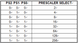
Enable watch-dog if set
Break Nuvoton W78E62 Flash Memory
Reduce Electro-magnetic interference can affect the process of Break Nuvoton W78E62 Flash Memory, Because of on-chip Flash EPROM, when a program is running in internal ROM space, the ALE will be unused. The transition of ALE will cause noise, so it can be turned off to reduce the EMI emission if it is useless.
Turning off the ALE signal transition only requires setting the bit 0 of the AUXR SFR, which is located at 08Eh. When ALE is turned off, it will be reactivated when the program accesses external ROM/RAM data or jumps to execute an external ROM code. The ALE signal will turn off again after it has been completely accessed or the program returns to internal ROM code space.
The AO bit in the AUXR register, when set, disables the ALE output. In order to reduce EMI emission from oscillation circuitry, W78E62 allows user to diminish the gain of on-chip oscillator amplifiers by using programmer to clear the B7 bit of security register.
Once B7 is set to 0, a half of gain will be decreased. Care must be taken if user attempts to diminish the gain of oscillator amplifier, reducing a half of gain may affect the external crystal operating improperly at high frequency above 24 MHz. The value of R and C1, C2 may need some adjustment while running at lower gain.
POF: Power off flag. Bit is set by hardware when power on reset. It can be cleared by software to determine chip reset is a warm boot or cold boot before Break Nuvoton W78E62 Flash Memory.
GF1, GF0: These two bits are general-purpose flag bits for the user. PD: Power down mode bit. Set it to enter power down mode. IDL: Idle mode bit. Set it to enter idle mode.
The power-off flag is located at PCON.4. This bit is set when VDD has been applied to the part. It can be used to determine if a reset is a warm boot or a cold boot if it is subsequently reset by software.
MC68HC05B6 microcontroller ic extract code
MC68HC05B6 microcontroller ic extract code
One example is MC68HC05B6 microcontroller ic extract code discussed above. If the power supply voltage is reduced by 50–70% for the period of time that the “AND $0100” instruction is executed, the CPU fetches an FFh value from the EEPROM memory rather than the actual value and this corresponds to the unsecured state of the fuse.
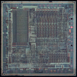
MC68HC05B6 microcontroller ic extract code
The trick is to carefully calculate the exact time to reduce the supply voltage, otherwise the CPU will stop functioning or go into the reset mode. This is not a difficult task, as the target instruction is executed within the first hundred cycles after the reset. Again, the attacker could use a pattern generator or build his own glitch device.
Reverse Engineering W78E52B Chip Data
First step to proceed with Reverse Engineering W78E52B Chip Data is to understand its main features and general description:
The W78E51B is an 8-bit microcontroller which can accommodate a wider frequency range with low power consumption. The instruction set for the W78E52B is fully compatible with the standard 8051. The W78E52B contains an 4K bytes Flash EPROM; a 128 bytes RAM; four 8-bit bi-directional and bit- addressable I/O ports; an additional 4-bit I/O port P4; two 16-bit timer/counters; a hardware watchdog timer and a serial port. These peripherals are supported by seven sources two-level interrupt capability. To facilitate programming and verification, the Flash EPROM inside the W78E52B allows the program memory to be programmed and read electronically. Once the code is confirmed, the user can protect the code for security.
The W78E51B microcontroller has two power reduction modes, idle mode and power-down mode, both of which are software selectable. The idle mode turns off the processor clock but allows for continued peripheral operation. The power-down mode stops the crystal oscillator for minimum power consumption. The external clock can be stopped at any time and in any state without affecting the processor.
Fully static design 8-bit CMOS microcontroller
Wide supply voltage of 4.5V to 5.5V
128 bytes of on-chip scratchpad RAM
4 KB On-chip Flash EPROM
64 KB program memory address space
64 KB data memory address space
Four 8-bit bi-directional ports
One extra 4-bit bit-addressable I/O port, additional INT2 / INT3 (available on 44-pin PLCC/QFP package)
Two 16-bit timer/counters
One full duplex serial port(UART)
Watchdog Timer
Seven sources, two-level interrupt capability
EMI reduction mode
Built-in power management
Code protection mechanism
Power glitches of IC Crack
Power supply voltage fluctuations can shift the threshold level of the transistors. As a result some flip-flops will sample their input at different time or the state of the security fuse will be read incorrectly. This is usually achieved by either increasing the power supply voltage or dropping it for a short period of time, normally from one to ten clock cycles. Power glitches can be applied to a microcontroller with any programming interface as they could affect both the CPU operation and the hardware security circuit. In general, they are harder to find and exploit than clock glitches because in addition to the timing parameters, the amplitude and rising/falling times are variables.
Posted in Break IC |
Tags: extract cpld ic bin, extract cpld ic code, extract cpld ic data, extract cpld ic eeprom, extract cpld ic hex |
Comments Closed
Nuvoton Microcontroller W77E058A Flash Memory Breaking
When we try to carry out the Nuvoton Microcontroller W77E058A Flash Memory Breaking, the electro-magnetic interference effect could be a problem for this process, Because of on-chip Flash EPROM, when a program is running in internal ROM space, the ALE will be unused.
The transition of ALE will cause noise, so it can be turned off to reduce the EMI emission if it is useless. Turning off the ALE signal transition only requires setting the bit 0 of the AUXR SFR, which is located at 08Eh. When ALE is turned off, it will be reactivated when the program accesses external ROM/RAM data or jumps to execute an external ROM code.
The ALE signal will turn off again after it has been completely accessed or the program returns to internal ROM code space. The AO bit in the AUXR register, when set, disables the ALE output. In order to reduce EMI emission from oscillation circuitry, W77E058A allows user to diminish the gain of on-chip oscillator amplifiers by using programmer to clear the B7 bit of security register from Nuvoton Microcontroller W77E058A Flash Memory Breaking.
Once B7 is set to 0, a half of gain will be decreased. Care must be taken if user attempts to diminish the gain of oscillator amplifier, reducing a half of gain may effect to external crystal operating improperly at high frequency above 24 MHz. The value of R and C1, C2 may need adjustment while running at lower gain.


POF:
Power off flag. Bit is set by hardware when power on reset. It can be cleared by software to determine chip reset is a warm boot or cold boot.
GF1, GF0: These two bits are general-purpose flag bits for the user. PD: Power down mode bit. Set it to enter power down mode. IDL: Idle mode bit. Set it to enter idle mode.
The power-off flag is located at PCON.4. This bit is set when VDD has been applied to the part. It can be used to determine if a reset is a warm boot or a cold boot if it is subsequently reset by software.
Clock Glitches Application
Applying clock glitches to some microcontrollers could be difficult. For example, the Texas Instruments MSP430 microcontroller family operates from an internal RC generator in bootloader mode and it is difficult to synchronise to the internal clock and estimate the exact time of the attack. Some smartcards benefit from having randomly inserted delays in the CPU instruction flow, which makes applying the attacks even more difficult. Using power analysis could help, but requires very sophisticated and expensive equipment to extract the reference signal in real time.