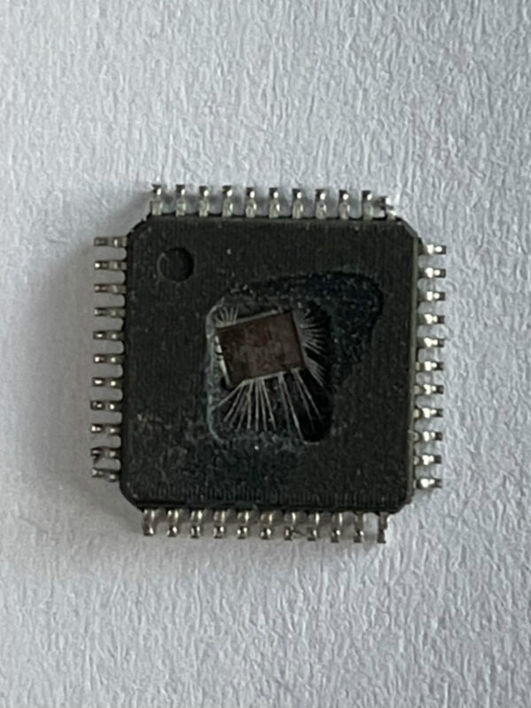
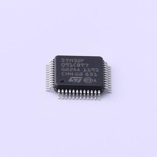
 Break Secured STM32F091CB MCU Flash Memory
Break Secured STM32F091CB MCU Flash Memory and extract embedded source code from stm32f091cb microcontroller flash memory, the binary program inside stm32f091cb microprocessor will be copied;
One standard I2S interface (multiplexed with SPI1) supporting four different audio standards can operate as master or slave at half-duplex communication mode. It can be configured to transfer 16 and 24 or 32 bits with16-bit or 32-bit data resolution and synchronized by a specific signal.
Audio sampling frequency from 8 kHz up to 192 kHz can be set by 8-bit programmable linear prescaler. When operating in master mode it can output a clock for an external audio component at 256 times the sampling frequency when recover flash binary from stm32f051c4 microcontroller.
An ARM SW-DP interface is provided to allow a serial wire debugging tool to be connected to the MCU.
PC13, PC14 and PC15 are supplied through the power switch. Since the switch only sinks a limited amount of current (3 mA), the use of GPIO PC13 to PC15 in output mode is limited: The speed should not exceed 2 MHz with a maximum load of 30 pF these GPIOs must not be used as a current sources (e.g. to drive an LED).
romper la memoria flash asegurada STM32F091CB MCU y extraer el código fuente embebido de la memoria flash del microcontrolador stm32f091cb, se copiará el programa binario dentro del microprocesador stm32f091cb;
After the first backup domain power-up, PC13, PC14 and PC15 operate as GPIOs. Their function then depends on the content of the Backup registers which is not reset by the main reset.
For details on how to manage these GPIOs, refer to the Battery backup domain and BKP register description sections in the STM32F05xx reference manual to restoring stm32f051c6 microprocessor flash heximal. This alternate feature is available on standard dies only.
After reset, these pins are configured as SWDAT and SWCLK alternate functions, and the internal pull-up on SWDAT pin and internal pull-down on SWCLK pin are activated.