 Break Microchip PIC18F4420 Microcontroller Memory
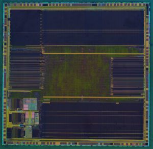
Break Microchip PIC18F4420 microcontroller memory including flash memory can help us extract protective PIC18F4420 microchip MCU embedded firmware content from its flash after disable the security fuse, restore binary file or heximal data of source code after decapsulate locked PIC18F4420 microprocessor;
Break Microchip PIC18F4420 microcontroller memory including flash memory can help us extract protective PIC18F4420 microchip MCU embedded firmware content from its flash after disable the security fuse, restore binary file or heximal data of source code after decapsulate locked PIC18F4420 microprocessor
PIC18F4420 devices incorporate three separate on-chip timers that help regulate the Power-on Reset process when Crack MCU eprom. Their main function is to ensure that the device clock is stable before code is executed which can be manipulated in the process of Break Microchip PIC18F4420 Microcontroller Memory. These timers are:
• Power-up Timer (PWRT)
• Oscillator Start-up Timer (OST)
• PLL Lock Time-out
The Power-up Timer (PWRT) of PIC18F4420 devices is an 11-bit counter which uses the INTRC source as the clock input. This yields an approximate time interval of 2048 x 32 s= 65.6 ms. While the PWRT is counting, the device is held in Reset to Recover IC ST62T65C6 Software.
The power-up time delay depends on the INTRC clock and will vary from chip-to-chip due to temperature and process variation. See DC parameter 33 for details.
Break Microchip PIC18F4420 Microcontroller Memory
The PWRT is enabled by clearing the PWRTEN Configuration bit.
The Oscillator Start-up Timer (OST) provides a 1024 oscillator cycle (from OSC1 input) delay after the PWRT delay is over (parameter 33). This ensures that the crystal or resonator oscillator has started and is stable enough to clock the controller by Read MCU PIC16F688 Software. More time may be required for the oscillator to meet its frequency tolerance specification.
quebrar a memória do microcontrolador Microchip PIC18F4420, incluindo memória flash, pode nos ajudar a extrair o conteúdo do firmware incorporado do microchip MCU protetor PIC18F4420 de seu flash após desativar o fusível de segurança, restaurar arquivo binário ou dados heximais do código-fonte após desencapsular o microprocessador PIC18F4420 bloqueado;
The OST time-out is invoked only for XT, LP, HS and HSPLL modes and only on Power-on Reset, or on exit from most power-managed modes.
przerwanie pamięci mikrokontrolera Microchip PIC18F4420, w tym pamięci flash, może pomóc nam wyodrębnić ochronną zawartość wbudowanego oprogramowania układowego MCU mikrochip PIC18F4420 z jego pamięci flash po wyłączeniu bezpiecznika zabezpieczającego, przywróceniu pliku binarnego lub danych szesnastkowych kodu źródłowego po dekapsulacji zablokowanego mikroprocesora PIC18F4420;
With the PLL enabled in its PLL mode, the time-out sequence following a Power-on Reset is slightly differ- ent from other oscillator modes. A separate timer is used to provide a fixed time-out that is sufficient for the PLL to lock to the main oscillator frequency to support the process of Read IC Microchip PIC32MX440F512H Binary. This PLL lock time-out (TPLL) is typically 2 ms and follows the oscillator start-up time-out.
casser la mémoire du microcontrôleur Microchip PIC18F4420, y compris la mémoire flash, peut nous aider à extraire le contenu du micrologiciel intégré de protection de la puce PIC18F4420 MCU de son flash après avoir désactivé le fusible de sécurité, restaurer le fichier binaire ou les données heximales du code source après avoir décapsulé le microprocesseur PIC18F4420 verrouillé ;