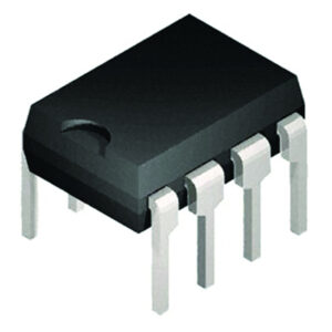
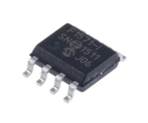
 Break Microchip PIC12F1571 MCU Protection
Break Microchip PIC12F1571 MCU Protection and read embedded firmware out from pic12f1571 microcontroller flash and eeprom memory, and then clone heximal program to new microprocessor PIC12F1571;

Break Microchip PIC12F1571 MCU Protection and read embedded firmware out from pic12f1571 microcontroller flash and eeprom memory, and then clone heximal program to new microprocessor PIC12F1571
PIC12F1257 microcontrollers combine the capabilities of 16-bit PWMs with Analog to suit a variety of applications. These devices deliver four 16-bit PWMs with independent timers for applications where high resolution is needed, such as LED lighting, stepper motors, power supplies and other general purpose applications which is useful.
The core independent peripherals (16-bit PWMs, Complementary Waveform Generator), Enhanced Universal Synchronous Asynchronous Receiver Transceiver (EUSART) and Analog (ADCs, Comparator and DAC) enable closed-loop feedback and communication for use in multiple market segments to restoring pic16f870 mcu heximal code.
The Peripheral Pin Select (PPS) functionality allows for I/O pin remapping of the digital peripherals for increased flexibility. The EUSART peripheral enables the communication for applications such as LIN.

Сломайте защиту микроконтроллера Microchip PIC12F1571 и прочитайте встроенную прошивку из флэш-памяти микроконтроллера pic12f1571 и памяти eeprom, а затем клонируйте шестнадцатеричную программу в новый микропроцессор PIC12F1571.
For the A/D converter to meet its specified accuracy, the charge holding capacitor (CHOLD) must be allowed to fully charge to the input channel voltage level. The analog input model is shown in Figure 17-2. The source impedance (RS) and the internal sampling switch (RSS) impedance directly affect the time required to charge the capacitor CHOLD by extracting mcu pic18f2520 embedded firmware.
The sampling switch (RSS) impedance varies over the device voltage (VDD). The source impedance affects the offset voltage at the analog input (due to pin leakage current). The maximum recommended impedance for analog sources is 2.5 kW. After the analog input channel is selected (changed), the channel must be sampled for at least the minimum acquisition time before starting a conversion.