Posts Tagged ‘quebrar circuito integrado code’
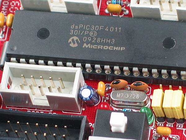
 Break MCU dsPIC30F4011 Heximal
The dsPIC30F4011 stands out due to its robust motor control features, including a high-speed PWM module, a dedicated motor control DSP engine, and multiple analog inputs. It’s favored in complex systems requiring real-time control and digital signal processing. Its protected memory design and built-in code protection features make it extremely difficult for unauthorized access, yet our techniques are built to overcome these barriers legally and ethically for rightful owners.
Our Capabilities: Reverse Engineering at the Hex Level
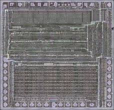
We offer a full-service solution to break, unlock, and extract the original heximal or binary file from a secured dsPIC30F4011. Our process involves:
- Disassembling and decoding memory architecture to gain access to protected areas.
- Decrypting secured blocks of flash or EEPROM.
- Reconstructing the program file into editable and compilable source code (where feasible).
- Providing cloning or duplication of the original firmware for use in replacement MCUs or system upgrades.
Whether the firmware is lost, corrupted, or needs to be modified without original source access, we help clients recover what they need with high accuracy.
Why Clients Choose Us
- Deep Expertise: Years of experience with Microchip microcontrollers, especially dsPIC family.
- Advanced Tools: We utilize a mix of proprietary hardware and software to access and process even the most secured memory regions.
- Confidentiality Assured: Every case is handled under strict NDAs, ensuring data privacy and intellectual property protection.
- Client-Centered Approach: From motor control firms to academic researchers, we tailor our services based on the actual needs of our clients.
Real-World Applications
Many users approach us when dealing with discontinued products, broken systems, or third-party devices that are no longer supported. Breaking the MCU dsPIC30F4011 heximal allows them to continue using or replicating critical systems—whether it’s industrial drives, robotic platforms, or power converters.
Conclusion
Recovering or cloning the firmware from a secured dsPIC30F4011 is not impossible—when done by the right hands. Our specialized service empowers clients to regain access to locked program files, ensuring operational continuity, custom development, or forensic analysis. If you need to unlock, hack, or duplicate your Microchip dsPIC30F4011 data, contact us today and let our experts handle the complex job with confidence and precision.
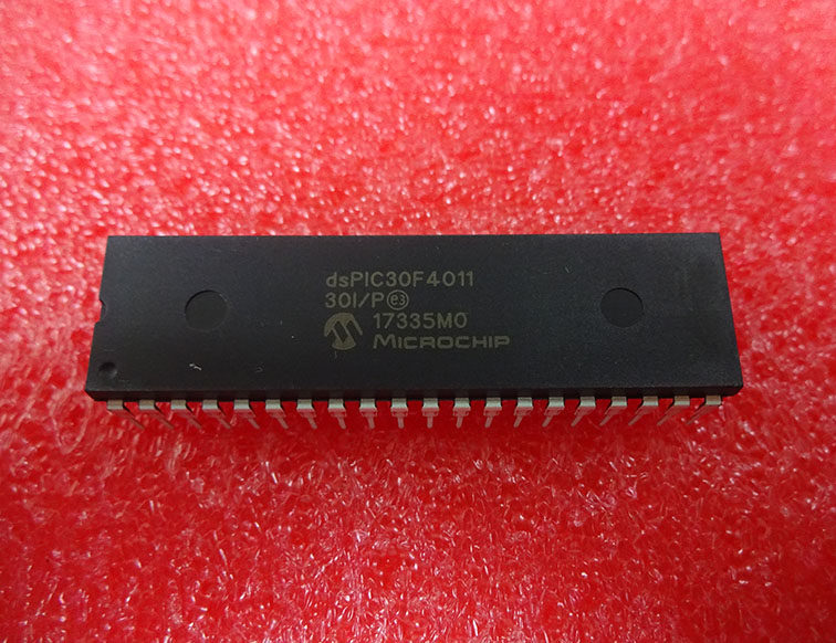
Break MCU dsPIC30F4011 memory and extract its Heximal out from its flash and eeprom, clone firmware to blank Microcontroller dsPIC30F4011 which will provide the same functions as original IC Clone;
Peripheral Features:
this group of dsPIC30F devices and is not intended to be a complete reference source. For more information on the CPU, peripherals, register descriptions and general device functionality, refer to the “dsPIC30F Family Reference Manual” (DS70046). For more information on the device instruction set and programming, refer to the “16-bit MCU and DSC Reference Manual” (DS70157).
High-Performance, Modified RISC CPU:
· Modified Harvard architecture
· C compiler optimized instruction set architecture with flexible addressing modes
· 83 base instructions
· 24-bit wide instructions, 16-bit wide data path
· 48 Kbytes on-chip Flash program space (16K instruction words)
· 2 Kbytes of on-chip data RAM
· 1 Kbyte of nonvolatile data EEPROM
· Up to 30 MIPS operation:
– DC to 40 MHz external clock input
– 4 MHz-10 MHz oscillator input with PLL active (4x, 8x, 16x)
· 30 interrupt sources:
– Three external interrupt sources
– Eight user-selectable priority levels for each
· High-current sink/source I/O pins: 25 mA/25 mA
· Timer module with programmable prescaler:
– Five 16-bit timers/counters; optionally pair 16-bit timers into 32-bit timer modules
· 16-bit Capture input functions
· 16-bit Compare/PWM output functions
· 3-wire SPI modules (supports 4 Frame modes)
· I2C™ module supports Multi-Master/Slave mode and 7-bit/10-bit addressing
· Two UART modules with FIFO Buffers
· CAN module, 2.0B compliant
Motor Control PWM Module Features:
· Six PWM output channels:
– Complementary or Independent Output modes
– Edge and Center-Aligned modes
· Three duty cycle generators
· Dedicated time base
· Programmable output polarity
· Dead-time control for Complementary mode
· Manual output control
· Trigger for A/D conversions
Quadrature Encoder Interface Module Features:
interrupt source
– Four processor trap sources
· 16 x 16-bit working register array
Phase A, Phase B and Index Pulse input 16-bit up/down position counter
Count direction status
Position Measurement (x2 and x4) mode
Programmable digital noise filters on inputs
Dual data fetch
Accumulator write-back for DSP operations
Alternate 16-bit Timer/Counter mode
Interrupt on position counter rollover/underflow
Modulo and Bit-Reversed Addressing modes
Two, 40-bit wide accumulators with optional saturation logic
Analog Features:
· 17-bit x 17-bit single-cycle hardware fractional/integer multiplier
· All DSP instructions are single cycle
· ±16-bit, single-cycle shift
· 10-bit Analog-to-Digital Converter (ADC) with four Sample and Holde (S&H) inputs:
– 1 Msps conversion rate
– Nine input channels
– Conversion available during Sleep and Idle
· Programmable Brown-out Reset only