 Recover MCU PIC18F2520 Binary
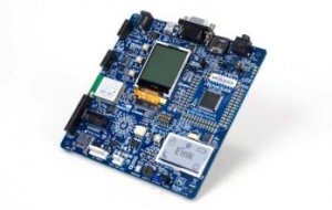
In the world of embedded systems, the MCU PIC18F2520 stands out as a powerful and reliable microcontroller widely used in automotive electronics, industrial automation, home appliances, and communication equipment. Its popularity stems from its robust performance, built-in EEPROM, and extensive I/O capabilities, making it ideal for real-time applications. However, what makes it secure for manufacturers also makes it difficult for end users to access or modify its internal firmware, especially when the chip is protected with fuse bits.

At CIRCUIT ENGINEERING CO., LTD, we offer advanced services to Recover MCU PIC18F2520 Binary, helping clients copy, clone, or duplicate the original program stored in the flash memory or EEPROM, even if the device is locked, encrypted, or secured. Whether you’ve lost the original source code, need to restore malfunctioning devices, or want to analyze existing data, we can help you unlock the chip and decode its contents with precision.
Recover MCU PIC18F2520 Binary from Microcontroller PIC18F2520 program memory, reset the security fuse bit inside the protective system from locked to unlocked one by Crack MCU PIC18F2520;
Many PIC18F2520 chips are shipped with fuse bits enabled, which disable standard read-out functions and make it nearly impossible to access the internal heximal firmware using traditional programmers. These protections are designed to prevent reverse engineering or unauthorized duplication, but they also pose significant challenges for legitimate developers and technicians needing to recover, modify, or migrate firmware to new hardware.

Our team is equipped with the tools and expertise required to crack these protections and bypass the fuse bits, allowing full access to the locked binary file. This process may involve decoding the archive stored in memory, reading from protected flash, or extracting the program data via low-level hardware or side-channel techniques.
Power Management Features:
Peripheral Highlights (Continued):
Run: CPU on, Peripherals on
Idle: CPU off, Peripherals on
Sleep: CPU off, Peripherals off
Ultra Low 50nA Input Leakage
Run mode Currents Down to 11 ìA Typical
Idle mode Currents Down to 2.5 ìA Typical
Sleep mode Current Down to 100 nA Typical
Timer1 Oscillator: 900 nA, 32 kHz, 2V
Watchdog Timer: 1.4 ìA, 2V Typical
Two-Speed Oscillator Start-up
Once the protected firmware is successfully extracted, we offer further services to convert the binary into human-readable formats. Our decryption pipeline includes transforming heximal data into assembly code, and in many cases, we can decompile the binary into partial or complete C source code.
This enables you to:
Restore damaged or bricked devices where firmware is corrupted or lost
Troubleshoot errors and bugs in legacy systems
Upgrade or modify existing embedded applications
Clone systems for mass production when the original code is unavailable
Perform security audits or validate device integrity
· Master Synchronous Serial Port (MSSP) module
Supporting 3-Wire SPI (all 4 modes) and I2C™
Master and Slave modes
· Enhanced Addressable USART module:
– Supports RS-485, RS-232 and LIN/J2602
– RS-232 operation using internal oscillator block (no external crystal required)
– Auto-wake-up on Start bit
– Auto-Baud Detect
· 10-Bit, up to 13-Channel Analog-to-Digital (A/D)

Flexible Oscillator Structure:
· Four Crystal modes, up to 40 MHz
· 4x Phase Lock Loop (PLL) – Available for Crystal and Internal Oscillators
· Two External RC modes, up to 4 MHz
· Two External Clock modes, up to 40 MHz
· Internal Oscillator Block:
– Fast wake from Sleep and Idle, 1 ìs typical
– 8 use-selectable frequencies, from 31 kHz to 8 MHz
– Provides a complete range of clock speeds from 31 kHz to 32 MHz when used with PLL
– User-tunable to compensate for frequency drift
· Secondary Oscillator using Timer1 @ 32 kHz
· Fail-Safe Clock Monitor:
– Allows for safe shutdown if peripheral clock stops
Peripheral Highlights:
Converter module:
– Auto-acquisition capability
– Conversion available during Sleep
· Dual Analog Comparators with Input Multiplexing
· Programmable 16-Level High/Low-Voltage
Detection (HLVD) module:
– Supports interrupt on High/Low-Voltage Detection
Special Microcontroller Features:
· C Compiler Optimized Architecture:
– Optional extended instruction set designed to
optimize re-entrant code
· 100,000 Erase/Write Cycle Enhanced Flash
Program Memory Typical
· 1,000,000 Erase/Write Cycle Data EEPROM
Memory Typical
· Flash/Data EEPROM Retention: 100 Years Typical
· Self-Programmable under Software Control
High-Current Sink/Source 25 mA/25 mA
Three Programmable External Interrupts
Four Input Change Interrupts
Up to 2 Capture/Compare/PWM (CCP) modules,
· Priority Levels for Interrupts
· 8 x 8 Single-Cycle Hardware Multiplier
· Extended Watchdog Timer (WDT):
– Programmable period from 4 ms to 131s one with Auto-Shutdown (28-pin devices)
· Enhanced Capture/Compare/PWM (ECCP) module (40/44-pin devices only):
– One, two or four PWM outputs
– Selectable polarity
– Programmable dead time
– Auto-shutdown and auto-restart
· Single-Supply 5V In-Circuit Serial
Programming™ (ICSP™) via Two Pins
· In-Circuit Debug (ICD) via Two Pins
· Wide Operating Voltage Range: 2.0V to 5.5V
· Programmable Brown-out Reset (BOR) with
Software Enable Option
The PIC18F2520 is used in a wide range of commercial and industrial systems. From automotive ECUs to industrial sensors and consumer electronics, our clients often need to open or duplicate protected firmware to ensure service continuity, compatibility, or quality control. When the manufacturer is no longer available or documentation is missing, we help recover the MCU PIC18F2520 binary, ensuring your hardware remains viable for years to come.
Let us help you take control of your embedded system’s firmware. Contact us to learn how we can unlock, decrypt, and restore what others consider impossible.