 Recover Mcu TS80C51U2 Flash
 May 25th, 2015 |
 Author:
Recover Mcu TS80C51U2 Flash
Recover Mcu TS80C51U2 Flash
We can Recover Mcu TS80C51U2 Flash, please view the Mcu TS80C51U2 features for your reference:
TS80C51U2 is high performance CMOS ROM, OTP and EPROM versions of the 80C51 CMOS single mcu 8-bit microcontroller. The TS80C51U2 retains all features of the 80C51 with extended ROM/EPROM capacity (16 Kbytes), 256 bytes of internal RAM, a 7-source , 4-level interrupt system, an on-mcu oscilator and three timer/counters. In addition, the TS80C51U2 has a second UART, enhanced functions on both UART, enhanced timer 2, a hardware watchdog timer, a dual data pointer, a baud rate generator and a X2 speed improvement mechanism. The fully static design of the TS80C51U2 allows to reduce system power consumption by bringing the clock frequency down to any value, even DC, without loss of data.
The TS80C51U2 has 2 software-selectable modes of reduced activity for further reduction in power consumption. In the idle mode the CPU is frozen while the timers, the serial port and the interrupt system are still operating. In the power-down mode the RAM is saved and all other functions are inoperative.
80C52 Compatible
8051 pin and instruction compatible
Four 8-bit I/O ports
Three 16-bit timer/counters
256 bytes scratchpad RAM
High-Speed Architecture
40 MHz @ 5V, 30MHz @ 3V
X2 Speed Improvement capability (6 clocks/machine cycle)
Recover Mcu TS80C51U2 Flash
30 MHz @ 5V, 20 MHz @ 3V (Equivalent to 60 MHz @ 5V, 40 MHz @ 3V) before Recover Mcu TS80C51U2 Flash
Second UART
Baud Rate Generator
Dual Data Pointer
On-mcu ROM/EPROM (16K-bytes)
Programmable Clock Out and Up/Down Timer/ Counter 2
Hardware Watchdog Timer (One-time enabled with Reset-Out)
Asynchronous port reset
Interrupt Structure with
7 Interrupt sources
4 level priority interrupt system
Full duplex Enhanced UARTs
Framing error detection
Automatic address recognition
Low EMI (inhibit ALE)
Power Control modes after Recover Mcu
Idle mode
Power-down mode
Power-off Flag
Once mode (On-mcu Emulation)
Power supply: 4.5-5.5V, 2.7-5.5V
Temperature ranges: Commercial (0 to 70oC) and
Industrial (-40 to 85oC)
Packages: PDIL40, PLCC44, VQFP44 1.4, CQPJ44 (window), CDIL40 (window)
 Posted in

Break MCU AT87LV51 Software
We can Break MCU AT87LV51 Software, please view the Mcu AT87LV51 features for your reference:
The AT87LV51 is a low-voltage, high-performance CMOS 8-bit mcu with 4K bytes of QuickFlash One-Time Programmable (OTP) memory when Recover MCU Microchip CF755 Dump. The device is manufactured using Atmel’s high-density nonvolatile memory technology and is compatible with the industry standard MCS-51 instruction set and pinout.
The on-chip QuickFlash allows the program memory to be user programmed by a conventional nonvolatile memory programmer. By combining a versatile 8-bit CPU with QuickFlash on a monolithic chip, the Atmel AT87LV51 is a powerful mcu that provides a highly flexible and cost-effective solution to many embedded control applications.
The AT87LV51 provides the following standard features: 4K bytes of QuickFlash OTP program memory, 128 bytes of RAM, 32 I/O lines, two 16-bit timer/counters, a five-vector, 2-level interrupt architecture, a full duplex serial port, on-chip oscillator, and clock circuitry. In addition, the AT87LV51 is designed with static logic for operation down to zero frequency and supports two software-selectable power-saving modes after Break MCU AT87LV51 Software.
The Idle mode stops the CPU while allowing the RAM, timer/counters, serial port and interrupt system to continue functioning. The Power-down mode saves the RAM contents but freezes the oscillator disabling all other chip functions until the next hardware reset. XTAL1 and XTAL2 are the input and output, respectively, of an inverting amplifier, which can be configured for use as an on-chip oscillator.
Either a quartz crystal or ceramic resonator may be used. To drive the device from an external clock source, XTAL2 should be left unconnected while XTAL1 is driven as shown in below Figure. There are no requirements on the duty cycle of the external clock signal, since the input to the internal clocking circuitry is through a divide-by-two flip-flop, but minimum and maximum voltage high and low time specifications must be observed.
Break MCU AT87LV51 Software
In Idle Mode, the CPU puts itself to sleep while all the on chip peripherals remain active. The mode is invoked by software. The content of the on-chip RAM and all the Special Function registers remains unchanged during this mode. The Idle mode can be terminated by any enabled interrupt or by a hardware reset when Break MCU AT87LV51 Software.
It should be noted that when Idle is terminated by a hardware reset, the device normally resumes program execution from where it left off, up to two machine cycles before the internal reset algorithm takes control. On-chip hardware inhibits access to internal RAM in this event to Unlock Microcontroller, but access to the port pins is not inhibited.
To eliminate the possibility of an unexpected write to a port pin when Idle is terminated by reset, the instruction following the one that invokes Idle should not be one that writes to a port pin or to external memory.
Recover Microcontroller ATtiny13A Heximal
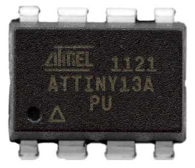
Recovering microcontroller ATtiny13A heximal involves a process of cracking or decoding the secured firmware stored in its flash memory and EEPROM memory of encrypted MCU ATtiny13A. The ATtiny13A, like many microcontrollers (MCUs), may have encrypted or locked firmware to protect its program and source code. However, using reverse engineering techniques, experts can break these ATtiny13A microprocessor’s protective layers and unlock the microprocessor’s memory to retrieve the heximal data.
Recovering microcontroller ATtiny13A heximal involves a process of cracking or decoding the secured firmware stored in its flash memory and EEPROM memory of encrypted MCU ATtiny13A. The ATtiny13A, like many microcontrollers (MCUs), may have encrypted or locked firmware to protect its program and source code. However, using reverse engineering techniques, experts can break these ATtiny13A microprocessor’s protective layers and unlock the microprocessor’s memory to retrieve the heximal data.
The recovery process starts by analyzing the microcontroller’s architecture to identify encryption protocols. Once these protections are bypassed, the binary or heximal firmware can be extracted. This data is essential for restoring or replicating the original program, enabling system recovery or hardware duplication.
Decoding or decrypting the ATtiny13A’s firmware allows developers to restore lost data or replicate the software for new devices. However, these actions must be conducted within legal and ethical guidelines to avoid violating intellectual property rights.
The AVR core combines a rich instruction set with 32 general purpose working registers which will provide benefit for Recover Microcontroller ATtiny13A Heximal. All 32 registers are directly connected to the Arithmetic Logic Unit (ALU), allowing two independent registers to be accessed in one single instruction executed in one clock cycle. The resulting architecture is more code efficient while achieving throughputs up to ten times faster than conventional CISC microcontrollers.
The ATtiny13A provides the following features: 1K byte of In-System Programmable Flash, 64 bytes EEPROM, 64 bytes SRAM, 6 general purpose I/O lines, 32 general purpose working registers, one 8-bit Timer/Counter with compare modes, Internal and External Interrupts, a 4-channel, 10-bit ADC, a programmable Watchdog Timer with internal Oscillator, and three software selectable power saving modes if Recover Microcontroller ATTINY13A Heximal.
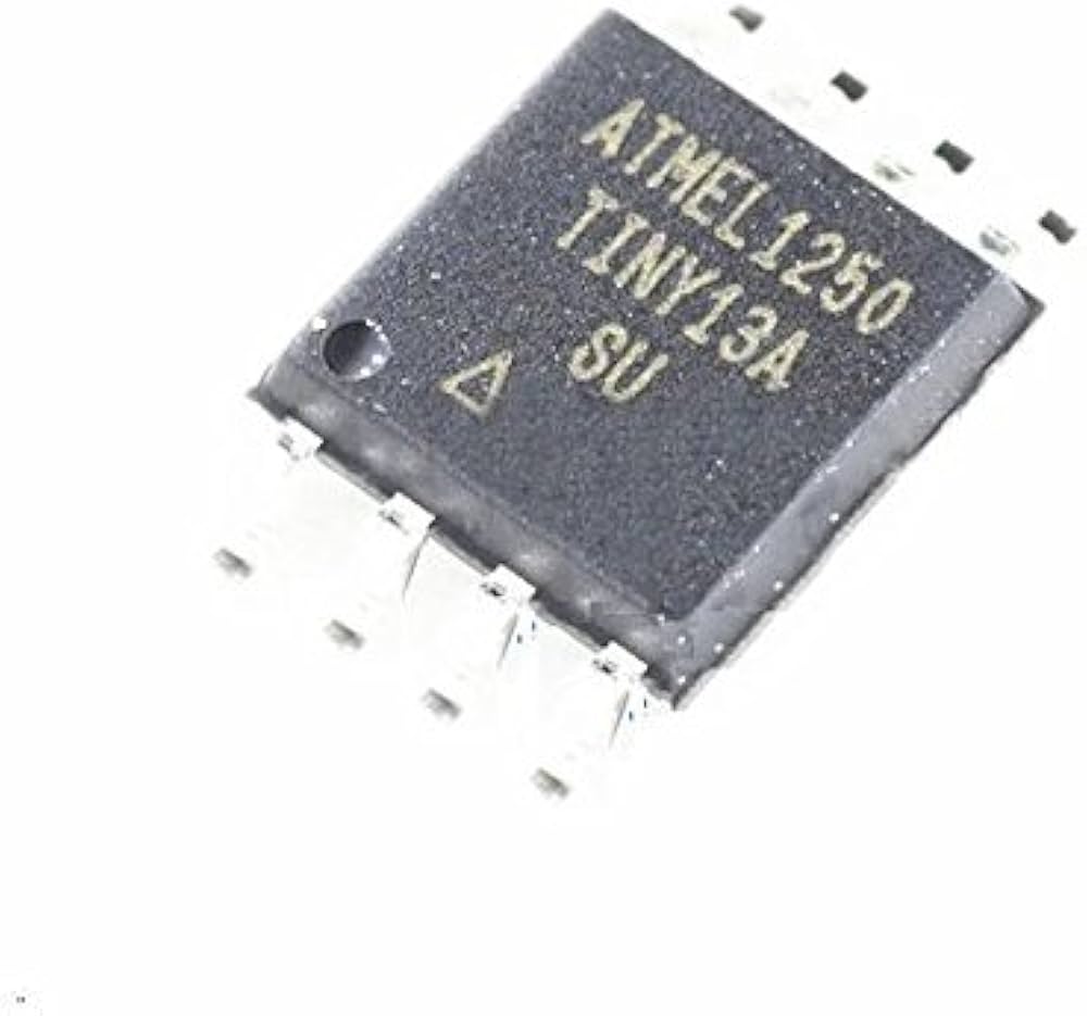
mbalekake microcontroller ATtiny13A heximal melu proses cracking utawa dekoding perangkat kukuh aman disimpen ing memori lampu kilat lan memori EEPROM saka ndhelik MCU ATtiny13A. ATtiny13A, kaya akeh mikrokontroler (MCU), bisa uga duwe perangkat kukuh sing dienkripsi utawa dikunci kanggo nglindhungi program lan kode sumber. Nanging, kanthi nggunakake teknik rekayasa terbalik, para ahli bisa ngilangi lapisan pelindung mikroprosesor ATtiny13A iki lan mbukak kunci memori mikroprosesor kanggo njupuk data heksimal.
The Idle mode stops the CPU while allowing the SRAM, Timer/Counter, ADC, Analog Comparator, and Interrupt system to continue functioning. The Power-down mode saves the register contents, disabling all chip functions until the next Interrupt or Hardware Reset. The ADC Noise Reduction mode stops the CPU and all I/O modules except ADC, to minimize switching noise during ADC conversions.
The device is manufactured using Atmel’s high density non-volatile memory technology. The On-chip ISP Flash allows the Program memory to be re-programmed In-System through an SPI serial interface, by a conventional non-volatile memory programmer or by an On-chip boot code running on the AVR core.
The ATtiny13A AVR is supported with a full suite of program and system development tools including: C Compilers, Macro Assemblers, Program Debugger/Simulators, and Evaluation kits if Recover MICROCONTROLLER.
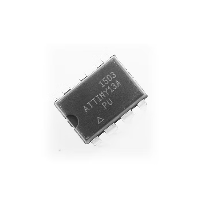
మైక్రోకంట్రోలర్ ATtiny13A హెక్సిమల్ని పునరుద్ధరించడం అనేది దాని ఫ్లాష్ మెమరీలో నిల్వ చేయబడిన సురక్షిత ఫర్మ్వేర్ మరియు ఎన్క్రిప్టెడ్ MCU ATtiny13A యొక్క EEPROM మెమరీని క్రాకింగ్ లేదా డీకోడింగ్ చేసే ప్రక్రియను కలిగి ఉంటుంది. ATtiny13A, అనేక మైక్రోకంట్రోలర్ల (MCUలు) వలె, దాని ప్రోగ్రామ్ మరియు సోర్స్ కోడ్ను రక్షించడానికి ఫర్మ్వేర్ను ఎన్క్రిప్ట్ చేసి లేదా లాక్ చేసి ఉండవచ్చు. అయినప్పటికీ, రివర్స్ ఇంజనీరింగ్ పద్ధతులను ఉపయోగించి, నిపుణులు ఈ ATtiny13A మైక్రోప్రాసెసర్ యొక్క రక్షణ పొరలను విచ్ఛిన్నం చేయవచ్చు మరియు హెక్సిమల్ డేటాను తిరిగి పొందడానికి మైక్రోప్రాసెసర్ మెమరీని అన్లాక్ చేయవచ్చు.
For compatibility with future devices, reserved bits should be written to zero if accessed. Reserved I/O memory addresses should never be written when Break IC PIC16F684 Binary.
I/O Registers within the address range 0x00 – 0x1F are directly bit-accessible using the SBI and CBI instructions. In these registers, the value of single bits can be checked by using the SBIS and SBIC instructions.ome of the Status Flags are cleared by writing a logical one to them. Note that, unlike most other AVRs, the CBI and SBI instructions will only operation the specified bit, and can therefore be used on registers containing such Status Flags. The CBI and SBI instructions work with registers 0x00 to 0x1F.
Recover Microcontroller ATtiny13A Heximal
This documentation contains simple code examples that briefly show how to use various parts of the device. These code examples assume that the part specific header file is included before compilation. Be aware that not all C compiler vendors include bit definitions in the header files and interrupt handling in C is compiler dependent. Please confirm with the C compiler documentation for more details.
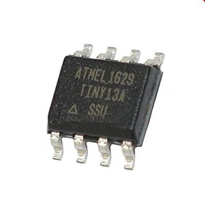
Die Wiederherstellung des Mikrocontrollers ATtiny13A Heximal umfasst einen Prozess zum Knacken oder Dekodieren der gesicherten Firmware, die im Flash-Speicher und EEPROM-Speicher des verschlüsselten MCU ATtiny13A gespeichert ist. Der ATtiny13A kann, wie viele Mikrocontroller (MCUs), eine verschlüsselte oder gesperrte Firmware haben, um sein Programm und seinen Quellcode zu schützen. Mithilfe von Reverse-Engineering-Techniken können Experten jedoch diese Schutzschichten des ATtiny13A-Mikroprozessors durchbrechen und den Speicher des Mikroprozessors entsperren, um die Heximal-Daten abzurufen.
Recover Microcontroller AT80F51 Eeprom
We can Recover Microcontroller AT80F51 Eeprom, please view the Microcontroller AT80F51 features for your reference:
The AT80F51 is a low-power, high-performance CMOS 8-bit microcomputer with 4K bytes of QuickFlash Memory. The device is manufactured using Atmel’s high density nonvolatile memory technology and is compatible with the industry standard MCS- 51™ instruction set and pinout.
The on-microcontroller QuickFlash allows custom codes to be quickly programmed in the factory. By combining a versatile 8-bit CPU with Quick-Flash on a monolithic microcontroller which carry out the same method as Recover MCU PIC16F876 Binary, the Atmel AT80F51 is a powerful microcomputer which provides a highly flexible and cost effective solution to many embedded control applications.
The AT80F51 provides the following standard features: 4K bytes of QuickFlash, 128 bytes of RAM, 32 I/O lines, two 16-bit timer/counters, a five vector two-level interrupt architecture, a full duplex serial port, on-microcontroller oscillator and clock circuitry. In addition, the AT80F51 is designed with static logic for operation down to zero frequency and supports two software selectable power saving modes through the purpose of Recover MCU PIC16F877 Heximal.
The Idle Mode stops the CPU while allowing the RAM, timer/counters, serial port and interrupt system to continue functioning. The Power Down Mode saves the RAM contents but freezes the oscillator disabling all other microcontroller functions until the next hardware reset.
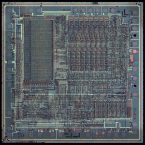
Recover Microcontroller AT80F51 Eeprom
XTAL1 and XTAL2 are the input and output, respectively, of an inverting amplifier which can be configured for use as an on-microcontroller oscillator, as shown in Figure 1. Either a quartz In idle mode, the CPU puts itself to sleep while all the on- microcontroller peripherals remain active. The mode is invoked by software.
The content of the on-microcontroller RAM and all the special functions registers remain unchanged during this mode. The idle mode can be terminated by any enabled interrupt or by a hardware reset. It should be noted that when idle is terminated by a hardware reset, the device normally resumes program execution when Crack MCU, from where it left off, up to two machine cycles before the internal reset algorithm takes control when Recover Microcontroller AT80F51 Eeprom.
On-microcontroller hardware inhibits access to internal RAM in this event, but access to the port pins is not inhibited. To eliminate the possibility of nated. The only exit from power down is a hardware reset. Reset redefines the SFRs but does not change the on-microcontroller RAM. The reset should not be activated before VCC is restored to its normal operating level and must be held active long enough to allow the oscillator to restart and stabilize.
Recover MCU PIC16HV540 Binary
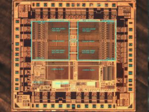
Recover MCU PIC16HV540 Binary
We can Recover MCU PIC16HV540 Binary, please view the MCU PIC16HV540 features for your reference:
High-Performance RISC CPU:
· Only 33 single word instructions to learn
· All instructions are single cycle (200 ns) except for program branches which are two-cycle
· Operating speed: DC – 20 MHz clock input DC – 200 ns instruction cycle
· 12-bit wide instructions
· 8-bit wide data path
· Seven special function hardware registers
· Four-level deep hardware stack
· Direct, indirect and relative addressing modes for data and instructions to Recover IC program
Peripheral Features:
· 8-bit real time clock/counter (TMR0) with 8-bit programmable prescaler
· Power-On Reset (POR)
· Brown-Out Protection
· Device Reset Timer (DRT) with short RC oscillator start-up time
· Programmable Watchdog Timer (WDT) with its own on-chip RC oscillator for reliable operation
· Sleep Timer
· 8 High Voltage I/O
· 4 Regulated I/O
· Wake up from SLEEP on-pin change
· Programmable code protection
· Power saving SLEEP mode
· Selectable oscillator options:
– RC: Low-cost RC oscillator
– XT: Standard crystal/resonator
– HS: High speed crystal/resonator
– LP: Power saving, low frequency crystal
· Glitch filtering on MCLR and pin change inputs
Recover MCU PIC16HV540 Binary
CMOS Technology:
· Selectable on-chip 3V/5V Regulator
· Low-power, high-speed CMOS EPROM technology for the purpose of Decrypt IC program
· Fully static design
· Wide-operating voltage range:
– 3.5V to 15V
· Temperature range:
– Commercial: 0°C to 70°C
– Industrial: -40°C to 85°C
· Low-power consumption
– < 2 mA typical @ 5V, 4 MHz
– 15 µA typical @ 3V, 32 kHz
– < 4.5 µA typical standby current @ 15V (with WDT disabled), 0°C to 70°C
The PIC16HV540 from Microchip Technology is a low- cost, high-performance, 8-bit, fully-static, EPROM- based CMOS microcontroller. It is pin and software compatible with the PIC16C5X family of devices. It employs a RISC architecture with only 33 single word single cycle instructions when Crack MCU. All instructions are single cycle except for program branches, which take two cycles. The PIC16HV540 delivers performance an order of magnitude higher than its competitors in the same price category after Recover MCU PIC16HV540 Binary.
The 12-bit wide instructions are highly orthogonal resulting in 2:1 code compression over other 8-bit microcontrollers in its class. The easy-to-use and easy-to-remember instruction set reduces development time significantly.
The PIC16HV540 is the first One-Time-Programmable (OTP) microcontroller with an on-chip 3 volt and 5 volt regulator. This eliminates the need for an external regulator in many applications powered from 9 Volt or 12 Volt batteries or unregulated 6 volt, 9 volt or 12 volt mains adapters.
The PIC16HV540 is ideally suited for applications that require very low standby current at high voltages. These typically require expensive low current regulators.
Break MCU PIC12CE674 Software
The high performance of the PIC12CE67X family can be attributed to a number of architectural features commonly found in RISC microprocessors which is critical part for Break MCU PIC12CE674 Software. To begin with, the PIC12CE67X uses a Harvard architecture, in which program and data are accessed from separate memories using separate buses.
This improves bandwidth over traditional von Neumann architecture in which program and data are fetched from the same memory using the same bus. Separating program and data buses also allow instructions to be sized differently than the 8-bit wide data word. Instruction opcodes are 14-bits wide making it possible to have all single word instructions.
A 14-bit wide program memory access bus fetches a 14-bit instruction in a single instruction cycle. A two-stage pipeline overlaps fetch and execution of instructions to facilitate the process of Copy MCU PIC18F4685 Software. Consequently, all instructions (35) execute in a single cycle (400 ns @ 10 MHz) except for program branches.
The table below lists program memory (EPROM), data memory (RAM), and non-volatile memory (EEPROM) for each PIC12C67X device. The PIC12C67X can directly or indirectly address its register files or data memory. All special function registers, including the program counter, are mapped in the data memory after Break MCU PIC12CE674 Software.
The PIC12C67X has an orthogonal (symmetrical) instruction set that makes it possible to carry out any operation on any register using any addressing mode to Crack MCU. This symmetrical nature and lack of ‘special optimal situations’ make programming with the PIC12C67X simple yet efficient.
In addition, the learning curve is reduced significantly. PIC12C67X devices contain an 8-bit ALU and working register. The ALU is a general purpose arithmetic unit. It performs arithmetic and Boolean functions between the data in the working register and any register file.
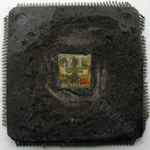
Break MCU PIC12CE674 Software
The ALU is 8-bits wide and capable of addition, subtraction, shift and logical operations. Unless otherwise mentioned, arithmetic operations are two’s complement in nature. In two-operand instructions, typically one operand is the working register (W register).
The other operand is a file register or an immediate constant. In single operand instructions, the operand is either the W register or a file register only after the completion of Recover IC PIC16F873 Heximal. The W register is an 8-bit working register used for ALU operations. It is not an addressable register.
Depending on the instruction executed, the ALU may affect the values of the Carry (C), Digit Carry (DC), and Zero (Z) bits in the STATUS register. The C and DC bits operate as a borrow bit and a digit borrow out bit, respectively, in subtraction. See the SUBLW and SUBWF instructions for examples.
Break Microcontroller PIC12C672 Heximal
The PIC12C67X devices are low-cost, high-performance, CMOS, fully-static, 8-bit microcontrollers with integrated analog-to-digital (A/D) converter and EEPROM data memory (EEPROM on PIC12CE67X versions only) when Break Microcontroller PIC12C672 Heximal.
All PICmicro® microcontrollers employ an advanced RISC architecture. The PIC12C67X microcontrollers have enhanced core features, eight-level deep stack, and multiple internal and external interrupt sources. The separate instruction and data buses of the Harvard architecture allow a 14-bit wide instruction word with the separate 8-bit wide data after IC Cloning. The two stage instruction pipeline allows all instructions to execute in a single cycle, except for program branches, which require two cycles.
Break Microcontroller PIC12C672 Heximal
A total of 35 instructions (reduced instruction set) are available. Additionally, a large register set gives some of the architectural innovations used to achieve a very high performance. PIC12C67X microcontrollers typically achieve a 2:1 code compression and a 4:1 speed improvement over other 8-bit microcontrollers in their class.
The PIC12C67X devices have 128 bytes of RAM, 16 bytes of EEPROM data memory (PIC12CE67X only), 5 I/O pins and 1 input pin. In addition a timer/counter is available. Also a 4-channel, high-speed, 8-bit A/D is provided. The 8-bit resolution is ideally suited for applications requiring low-cost analog interface which can be used for MC68HC05B6 microcontroller ic extract code, (i.e., thermostat control, pressure sensing, etc.) before Break MICROCONTROLLER
The PIC12C67X devices have special features to reduce external components, thus reducing cost, The PIC12C67X products are compatible with other members of the 14-bit PIC16CXXX families. enhancing system reliability and reducing power consumption.
The Power-On Reset (POR), Power-up Timer (PWRT), and Oscillator Start-up Timer (OST) eliminate the need for external reset circuitry. There are five oscillator configurations to choose from, including INTRC precision internal oscillator mode and the power-saving LP (Low Power) oscillator mode when Extract PIC16F84 MCU firmware. Power-saving SLEEP mode, Watchdog Timer and code protection features improve system cost, power and reliability.
The SLEEP (power-down) feature provides a power-saving mode. The user can wake-up the chip from SLEEP through several external and internal interrupts and resets when Break Microcontroller PIC12C672 Heximal.
Break IC PIC12C671 Eeprom
We can Break IC PIC12C671 Eeprom, please view the IC PIC12C671 features for your reference:
High-Performance RISC CPU:
· Only 35 single word instructions to learn
· All instructions are single cycle (400 ns) except for program branches which are two-cycle
· Operating speed: DC – 10 MHz clock input DC – 400 ns instruction cycle
· 14-bit wide instructions 8-bit wide data path
· Interrupt capability
· Special function hardware registers
· 8-level deep hardware stack
· Direct, indirect and relative addressing modes for data and instructions to facilitate the process of Extract PLD IC Firmware
Peripheral Features:
· Four-channel, 8-bit A/D converter
· 8-bit real time clock/counter (TMR0) with 8-bit programmable prescaler
· 1,000,000 erase/write cycle EEPROM data memory
· EEPROM data retention > 40 years
Special Microcontroller Features:
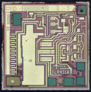
Break IC PIC12C671 Eeprom
In-Circuit Serial Programming (ICSP™)
Internal 4 MHz oscillator with programmable calibration
Selectable clockout
Power-on Reset (POR)
Power-up Timer (PWRT) and Oscillator Start-up Timer (OST)
Watchdog Timer (WDT) with its own on-chip RC oscillator for reliable operation in order to Extract PLD MCU code
Power saving SLEEP mode
Interrupt-on-pin change (GP0, GP1, GP3)
Internal pull-ups on I/O pins (GP0, GP1, GP3)
Internal pull-up on MCLR pin
Selectable oscillator options:
– INTRC: Precision internal 4 MHz oscillator
– EXTRC: External low-cost RC oscillator
– XT: Standard crystal/resonator
– HS: High speed crystal/resonator after Break IC PIC12C671 Eeprom
– LP: Power saving, low frequency crystal
CMOS Technology:
· Low-power, high-speed CMOS EPROM/EEPROM technology
· Fully static design to against the process of MCU Cracking
· Wide operating voltage range 2.5V to 5.5V
· Commercial, Industrial and Extended temperature ranges
· Low power consumption
< 2 mA @ 5V, 4 MHz
15 µA typical @ 3V, 32 kHz
< 1 µA typical standby current
Break MCU PIC16F876 Flash
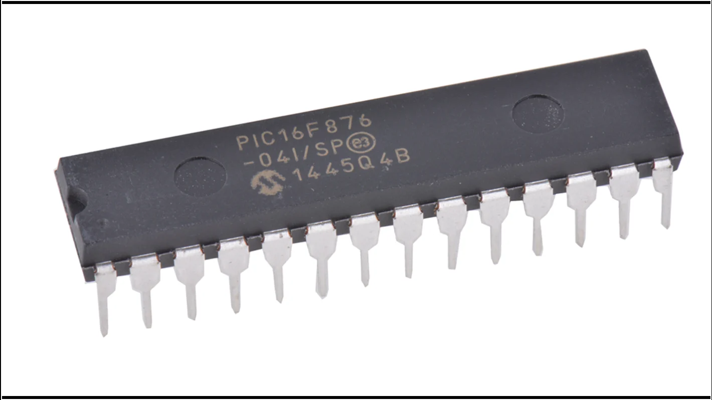
Breaking MCU PIC16F876 flash involves cracking the encrypted and secured firmware stored in its flash memory and EEPROM memory. This secured PIC16F876 microcontroller unit (MCU) is often used in embedded systems, where its firmware and software are protected to prevent unauthorized access. When attempting to break the protection, reverse engineering techniques are typically employed to decode or decrypt the encrypted PIC16F876 microprocessor’s locked binary and heximal data within the flash memory.
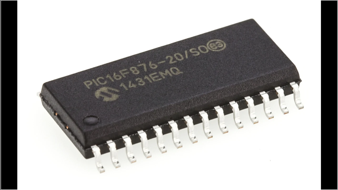
break MCU PIC16F876 lampu kilat melu retak perangkat kukuh ndhelik lan aman disimpen ing memori lampu kilat lan memori EEPROM. Unit mikrokontroler (MCU) PIC16F876 sing aman iki asring digunakake ing sistem sing dipasang, ing ngendi perangkat kukuh lan piranti lunak dilindhungi kanggo nyegah akses sing ora sah. Nalika nyoba ngrusak proteksi, teknik reverse engineering biasane digunakake kanggo decode utawa dekripsi data biner lan heksimal mikroprosesor PIC16F876 sing dikunci ing memori lampu kilat.
The process begins with analyzing the microprocessor’s architecture to identify and bypass the encryption protocols securing the firmware. Specialized tools are used to attack the encryption and unlock the flash memory, allowing access to the embedded program and source code. Once the protective measures are defeated, the firmware can be restored, cloned, or replicated for system diagnostics, repair, or further development.
Unlocking the PIC16F876 MCU’s flash memory allows for the recovery of critical software, which is particularly useful in situations where the original source code is lost, corrupted, or unavailable. Cloning the firmware ensures that the program can be duplicated for use in similar systems or to create backups for future use.
MCU PIC16F876 ఫ్లాష్ను విచ్ఛిన్నం చేయడంలో దాని ఫ్లాష్ మెమరీ మరియు EEPROM మెమరీలో నిల్వ చేయబడిన ఎన్క్రిప్టెడ్ మరియు సురక్షిత ఫర్మ్వేర్ను క్రాక్ చేయడం ఉంటుంది. ఈ సురక్షిత PIC16F876 మైక్రోకంట్రోలర్ యూనిట్ (MCU) తరచుగా ఎంబెడెడ్ సిస్టమ్లలో ఉపయోగించబడుతుంది, ఇక్కడ అనధికార ప్రాప్యతను నిరోధించడానికి దాని ఫర్మ్వేర్ మరియు సాఫ్ట్వేర్ రక్షించబడతాయి. రక్షణను విచ్ఛిన్నం చేయడానికి ప్రయత్నించినప్పుడు, ఫ్లాష్ మెమరీలో గుప్తీకరించిన PIC16F876 మైక్రోప్రాసెసర్ యొక్క లాక్ చేయబడిన బైనరీ మరియు హెక్సిమల్ డేటాను డీకోడ్ చేయడానికి లేదా డీక్రిప్ట్ చేయడానికి రివర్స్ ఇంజనీరింగ్ పద్ధతులు సాధారణంగా ఉపయోగించబడతాయి.
However, it is crucial to note that breaking the protection of an MCU like the PIC16F876 should be done within legal and ethical boundaries. Unauthorized decryption or cloning of the firmware could lead to intellectual property violations and legal consequences. As such, this process should be carried out responsibly, ensuring the preservation of both the software’s integrity and the rights of the original creators.
The STATUS register contains the arithmetic status of the ALU, the RESET status and the bank select bits for data memory. The STATUS register can be the destination for any instruction, as with any other register. If the STATUS register is the destination for an instruction that affects the Z, DC or C bits, then the write to these three bits is disabled.
These bits are set or cleared according to the device logic. Furthermore, the TO and PD bits are not writable, therefore, the result of an instruction with the STATUS register as destination may be different than intended for the purpose of Break IC SST89E58RD2A Software.
Break Mcu PIC16F876 Flash
For example, CLRF STATUS will clear the upper three bits and set the Z bit. This leaves the STATUS register as 000u u1uu (where u = unchanged). It is recommended, therefore, that only BCF, BSF, SWAPF and MOVWF instructions are used to alter the STATUS register, because these instructions do not affect the Z, C or DC bits from the STATUS register.
For other instructions not affecting any status bits, see the “Instruction Set Summary.”
The OPTION_REG Register is a breakable and writable register, which contains various control bits to configure the TMR0 prescaler/WDT postscaler (single assignable register known also as the prescaler), the External INT Interrupt, TMR0 and the weak pull-ups on PORTB.
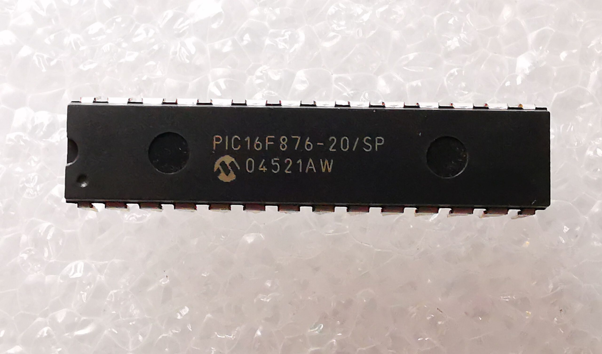
Um den Flash-Speicher des MCU PIC16F876 zu knacken, muss die verschlüsselte und gesicherte Firmware geknackt werden, die in seinem Flash-Speicher und EEPROM-Speicher gespeichert ist. Diese gesicherte Mikrocontrollereinheit (MCU) PIC16F876 wird häufig in eingebetteten Systemen verwendet, in denen die Firmware und Software vor unbefugtem Zugriff geschützt sind. Beim Versuch, den Schutz zu knacken, werden normalerweise Reverse-Engineering-Techniken eingesetzt, um die gesperrten binären und hexadezimalen Daten des verschlüsselten Mikroprozessors PIC16F876 im Flash-Speicher zu dekodieren oder zu entschlüsseln.
The program counter (PC) is 13-bits wide. The low byte comes from the PCL register, which is a breakable and writable register. The upper bits (PC<12:8>) are not breakable, but are indirectly writable through the PCLATH register to facilitate the process of Recover MCU DSPIC30F6013A30IP Firmware. On any RESET, the upper bits of the PC will be cleared. Figure 2-5 shows the two situations for the loading of the PC.
The upper example in the figure shows how the PC is loaded on a write to PCL (PCLATH<4:0> → PCH). The lower example in the figure shows how the PC is loaded during aCALL orGOTO instruction (PCLATH<4:3> → PCH). All PIC16F87X devices are capable of addressing a continuous 8K word block of program memory which is critical for Microcontroller Unlocking.
Break IC PIC16F876 Flash
The CALL and GOTO instructions provide only 11 bits of address to allow branching within any 2K program memory page. When doing aCALL or GOTO instruction, the upper 2 bits of the address are provided by PCLATH<4:3>. When doing a CALL or GOTO instruction, the user must ensure that the page select bits are programmed so that the desired program memory page is addressed before Break Mcu PIC16F876 Flash
If a return from a CALL instruction (or interrupt) is executed, the entire 13-bit PC is popped off the stack. Therefore, manipulation of the PCLATH<4:3> bits is not required for the return instructions (which POPs the address from the stack).
Break IC PIC16F873 Software
Breaking IC PIC16F873 software involves a series of techniques aimed at decrypting or cracking the encrypted firmware stored in its flash memory and EEPROM memory. The PIC16F873 microcontroller (MCU) is designed with secured protections that make its software, including binary and heximal data, difficult to access without proper authorization. However, reverse engineering and decryption techniques can be employed to unlock the locked firmware, enabling the extraction of the embedded program or source code for legitimate purposes.
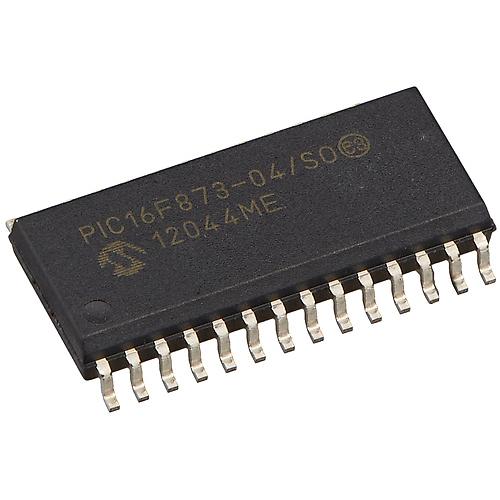
IC PIC16F873 yazılımını kırmak, flaş belleğinde ve EEPROM belleğinde saklanan şifreli aygıt yazılımını şifresini çözmeyi veya kırmayı amaçlayan bir dizi tekniği içerir. Güvenli PIC16F873 mikrodenetleyicisi (MCU), ikili ve onaltılık veriler de dahil olmak üzere yazılımına uygun yetkilendirme olmadan erişilmesini zorlaştıran güvenli korumalarla tasarlanmıştır. Ancak, kilitli mikroişlemci PIC16F873 tersine mühendislik ve şifre çözme teknikleri, kilitli aygıt yazılımını kilidini açmak için kullanılabilir ve gömülü programın veya kaynak kodunun meşru amaçlar için çıkarılmasını sağlar.
To begin the process, an attacker must first analyze the microprocessor’s architecture to understand how the protective mechanisms work. This may include studying the microcomputer’s memory layout, security features, and encryption algorithms. Once the firmware is identified, specialized tools and methods are used to break or crack the encryption, allowing the software to be decoded and recovered.
The goal of breaking the IC PIC16F873 software is often to restore functionality or replicate the program for backup purposes. In some cases, the source code is extracted to troubleshoot issues or enhance the program’s performance. Additionally, when cloning the software for use in other devices, the goal is to duplicate the program exactly as it exists in the original system.
However, it is crucial to note that breaking the software of an MCU like the PIC16F873 must be done within legal and ethical boundaries. Unauthorized access to locked firmware or decryption of encrypted data can violate intellectual property laws and lead to legal consequences.
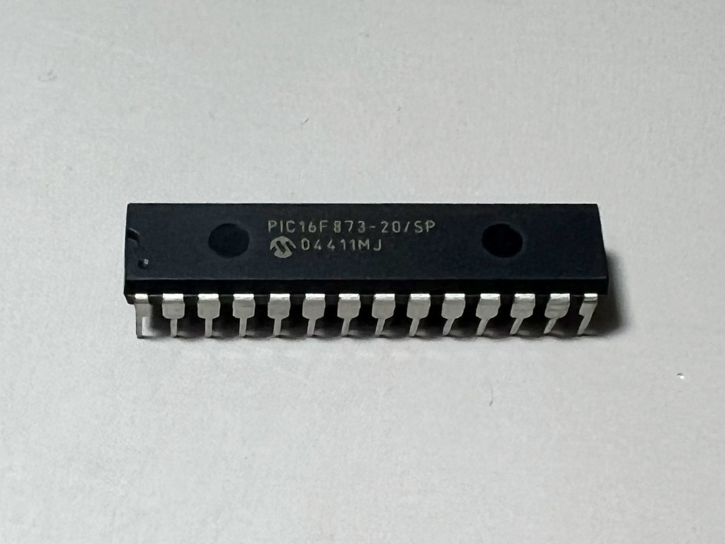
การทำลายซอฟต์แวร์ IC PIC16F873 เกี่ยวข้องกับเทคนิคชุดหนึ่งที่มุ่งเป้าไปที่การถอดรหัสหรือแคร็กเฟิร์มแวร์ที่เข้ารหัสซึ่งเก็บไว้ในหน่วยความจำแฟลชและหน่วยความจำ EEPROM ไมโครคอนโทรลเลอร์ (MCU) PIC16F873 ที่ปลอดภัยได้รับการออกแบบด้วยการป้องกันที่ปลอดภัยซึ่งทำให้ซอฟต์แวร์ซึ่งรวมถึงข้อมูลไบนารีและเลขฐานสิบหกเข้าถึงได้ยากหากไม่ได้รับอนุญาตอย่างเหมาะสม อย่างไรก็ตาม สามารถใช้เทคนิควิศวกรรมย้อนกลับและการถอดรหัสของไมโครโปรเซสเซอร์ PIC16F873 เพื่อปลดล็อกเฟิร์มแวร์ที่ถูกล็อค ทำให้สามารถแยกโปรแกรมที่ฝังไว้หรือโค้ดต้นฉบับเพื่อวัตถุประสงค์ที่ถูกต้องได้
In summary, breaking the IC PIC16F873 software involves cracking encryption, decoding binary data, and reverse engineering the firmware to access or restore critical software, while always adhering to ethical and legal standards.
We can Break IC PIC16F873 Software, please view the IC PIC16F873 features for your reference:
· High performance RISC CPU
· Only 35 single word instructions to learn
· All single cycle instructions except for program branches which are two cycle
· Operating speed: DC – 20 MHz clock input DC – 200 ns instruction cycle
· Up to 8K x 14 words of FLASH Program Memory, Up to 368 x 8 bytes of Data Memory (RAM) Up to 256 x 8 bytes of EEPROM Data Memory after the process of Break Microcontroller PIC16F767 Firmware
· Pinout compatible to the PIC16C73B/74B/76/77
· Interrupt capability (up to 14 sources)
· Eight level deep hardware stack
· Direct, indirect and relative addressing modes
· Power-on Reset (POR)
· Power-up Timer (PWRT) and Oscillator Start-up Timer (OST)
· Watchdog Timer (WDT) with its own on-chip RC oscillator for reliable operation
· Programmable code protection
· Power saving SLEEP mode
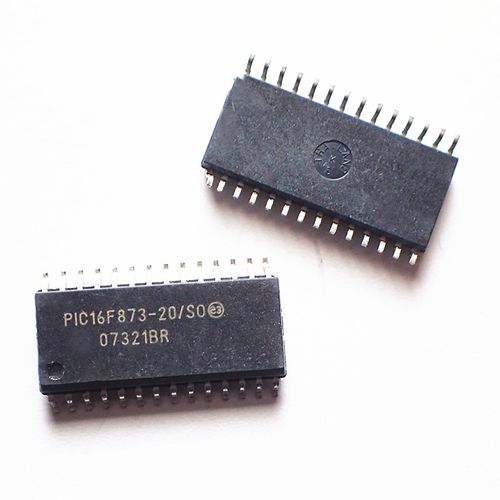
Phá vỡ phần mềm IC PIC16F873 liên quan đến một loạt các kỹ thuật nhằm giải mã hoặc bẻ khóa phần mềm được mã hóa được lưu trữ trong bộ nhớ flash và bộ nhớ EEPROM của nó. Bộ vi điều khiển (MCU) PIC16F873 được bảo mật được thiết kế với các biện pháp bảo vệ an toàn khiến phần mềm của nó, bao gồm dữ liệu nhị phân và thập lục phân, khó có thể truy cập nếu không có sự cho phép thích hợp. Tuy nhiên, kỹ thuật giải mã và kỹ thuật đảo ngược bộ vi xử lý PIC16F873 bị khóa có thể được sử dụng để mở khóa phần mềm bị khóa, cho phép trích xuất chương trình nhúng hoặc mã nguồn cho các mục đích hợp pháp.
· Selectable oscillator options
· Low power, high speed CMOS FLASH/EEPROM technology
· Fully static design
· In-Circuit Serial Programming (ICSP) via two pins
· Single 5V In-Circuit Serial Programming capability
· In-Circuit Debugging via two pins
· Processor break/write access to program memory by Break Chip PIC16F720 Firmware
· Wide operating voltage range: 2.0V to 5.5V
· High Sink/Source Current: 25 mA
· Commercial, Industrial and Extended temperature ranges
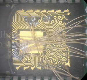
Break IC PIC16F873 Software
· Low-power consumption:
– < 0.6 mA typical @ 3V, 4 MHz
– 20 µA typical @ 3V, 32 kHz
– < 1 µA typical standby current
Peripheral Features:
· Timer0: 8-bit timer/counter with 8-bit prescaler
· Timer1: 16-bit timer/counter with prescaler, can be incremented during SLEEP via external crystal/clock
· Timer2: 8-bit timer/counter with 8-bit period register, prescaler and postscaler
· Two Capture, Compare, PWM modules
– Capture is 16-bit, max. resolution is 12.5 ns
– Compare is 16-bit, max. resolution is 200 ns
– PWM max. resolution is 10-bit
· 10-bit multi-channel Analog-to-Digital converter can provide a critical part for Microcontroller Unlock
· Synchronous Serial Port (SSP) with SPI (Master mode) and I2C (Master/Slave)
· Universal Synchronous Asynchronous Receiver Transmitter (USART/SCI) with 9-bit address detection
· Parallel Slave Port (PSP) 8-bits wide, with external RD, WR and CS controls (40/44-pin only)
· Brown-out detection circuitry for Brown-out Reset (BOR)