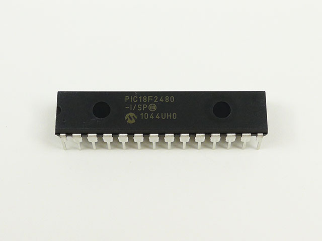
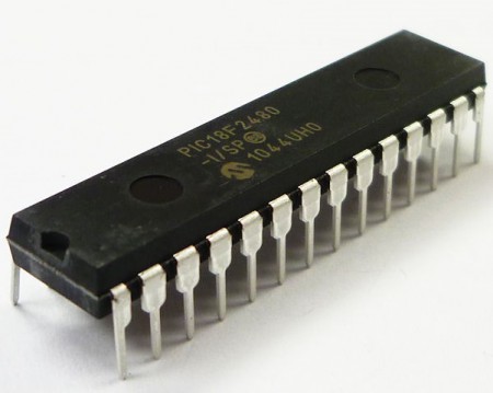
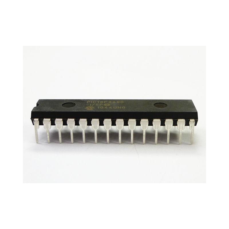
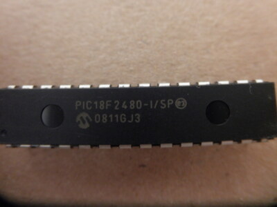
 Copy MCU PIC18F2480 Program
When legacy hardware fails, source files are lost, or manufacturers no longer support a product, retrieving the embedded program becomes mission-critical. Our service, centered on the keyword Copy MCU PIC18F2480 Program, helps end users restore, copy, clone, or duplicate protected firmware from Microchip PIC18F2480-based devices. We focus on lawful recovery, compatibility, and preserving device integrity while working with protected, locked, encrypted, or secured embedded program data stored in flash and EEPROM memory.
Why clients need this service
The PIC18F2480 is widely used in industrial controllers, consumer electronics, instrumentation, automotive modules, and medical peripherals thanks to its balance of performance and peripheral features. Common client needs include:
- Restoring a heximal or binary firmware file from a failing device.
- Recovering lost program or archive data for maintenance and audits.
- Cloning or duplicating firmware to support production scaling or legacy replacements.
- Performing compatibility testing, security audits, or lawful reverse engineering for interoperability.
We can Copy MCU PIC18F2480 Program, below MCU PIC18F2480 features for your reference:
Power-Managed Modes:
Peripheral Highlights:
Run: CPU on, Peripherals on
Idle: CPU off, Peripherals on
Sleep: CPU off, Peripherals off
Idle mode Currents Down to 6.1 ìA Typical
Sleep mode Current Down to 0.2 ìA Typical
Timer1 Oscillator: 1 ìA, 32 kHz, 2V
Watchdog Timer: 1.7 ìA
Two-Speed Oscillator Start-up
High-Current Sink/Source 25 mA/25 mA
Three External Interrupts
One Capture/Compare/PWM (CCP) module
Enhanced Capture/Compare/PWM (ECCP) module
(40/44-pin devices only):
– One, two or four PWM outputs
– Selectable polarity
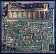
The PIC18F2480 family offers a robust 8-bit architecture with enhanced instruction efficiency, on-chip flash for program storage, EEPROM for non-volatile data, and multiple communication/peripheral interfaces. These characteristics make it ideal for embedded control tasks but also mean manufacturers often enable protective fuse bits or other safeguards to protect intellectual property.
Our approach (high-level, non-actionable)
Extracting and reconstructing firmware is a sensitive activity that must protect intellectual property and follow legal boundaries. Below are the general phases we follow — described conceptually rather than as step-by-step instructions:
- Legal & authorization check — Confirm ownership or proper authorization to access and duplicate the firmware.
- Device assessment — Identify the exact MCU revision, memory map, and protection status to plan a safe process.
- Non-destructive extraction attempts — Use proven, minimally invasive techniques to read accessible flash/eeprom contents where permitted.
- Protection analysis — Evaluate whether the device is locked, encrypted, or secured, and determine legitimate options for recovery that respect legal constraints.
- Data recovery & integrity verification — Restore the extracted binary/heximal data and verify checksums and functionality in controlled test environments.
- Disassembly & reconstruction — Where needed, convert the extracted program into readable assembly and, where feasible, reconstruct higher-level representations suitable for debugging or migration (note: we don’t publish methods for circumventing protections).
- Delivery & support — Provide the recovered program/file/source-code artifacts, documentation, and optional engineering services to port or harden firmware for future resilience.
– Programmable dead time
Flexible Oscillator Structure:
· Four Crystal modes, up to 40 MHz
· 4x Phase Lock Loop (PLL) – Available for Crystal and Internal Oscillators)
· Two External RC modes, up to 4 MHz
· Two External Clock modes, up to 40 MHz
· Internal Oscillator Block:
– Fast wake from Sleep and Idle, 1 ìs typical
– Provides a complete range of clock speeds, from 31 kHz to 32 MHz when used with PLL
– User-tunable to compensate for frequency drift
· Secondary Oscillator using Timer1 @ 32 kHz
· Fail-Safe Clock Monitor
– Auto-shutdown and auto-restart
Master Synchronous Serial Port (MSSP) module
Supporting 3-Wire SPI (all 4 modes) and I2C™
Master and Slave modes
Enhanced Addressable USART module
– Supports RS-485, RS-232 and LIN/J2602
– RS-232 operation using internal oscillator block
– Auto-wake-up on Start bit
– Auto-Baud Detect
10-Bit, up to 11-Channel Analog-to-Digital
Converter (A/D) module, up to 100 ksps
– Auto-acquisition capability
– Conversion available during Sleep
Dual Analog Comparators with Input Multiplexing
– Allows for safe shutdown if peripheral clock stops
Special Microcontroller Features:
· C Compiler Optimized Architecture with Optional Extended Instruction Set to Crack MCU
· 100,000 Erase/Write Cycle Enhanced Flash Program Memory Typical
· 1,000,000 Erase/Write Cycle Data EEPROM Memory Typical
· Flash/Data EEPROM Retention: > 40 Years
· Self-Programmable under Software Control
· Priority Levels for Interrupts
· 8 x 8 Single-Cycle Hardware Multiplier
· Extended Watchdog Timer (WDT):
– Programmable period from 41 ms to 131s
· Single-Supply 5V In-Circuit Serial Programming™ (ICSP™) via Two Pins
· In-Circuit Debug (ICD) via Two Pins
· Wide Operating Voltage Range: 2.0V to 5.5V if Copy MCU
What we deliver
- Recovered firmware in hex or binary formats.
- Verified memory archive dumps (flash, EEPROM).
- Analysis reports describing protection status and practical options for lawful recovery.
- Support to restore, clone, duplicate, or unlock firmware where legally allowed.
Responsible, expert service
Our emphasis is on responsible handling of protected embedded systems: restoring value to aging equipment, enabling lawful interoperability, and helping engineers move forward when original source code is gone. If you need to Copy MCU PIC18F2480 Program or recover firmware from PIC18F2480-based hardware, we can help—securely, professionally, and respectfully of legal boundaries.
ECAN Technology Module Features:
· Message Bit Rates up to 1 Mbps
· Conforms to CAN 2.0B Active Specification
· Fully Backward Compatible with PIC18XXX8 CAN modules
· Three Modes of Operation:
– Legacy, Enhanced Legacy, FIFO
· Three Dedicated Transmit Buffers with Prioritization
· Two Dedicated Receive Buffers
· Six Programmable Receive/Transmit Buffers
· Three Full 29-Bit Acceptance Masks
· 16 Full 29-Bit Acceptance Filters w/Dynamic Association
· DeviceNet™ Data Byte Filter Support
· Automatic Remote Frame Handling
· Advanced Error Management Features