 Reverse engineering MCU ATMEGA48PV Code
We can Reverse engineering MCU ATMEGA48PV Code, please view the MCU ATMEGA48PV features for your reference:
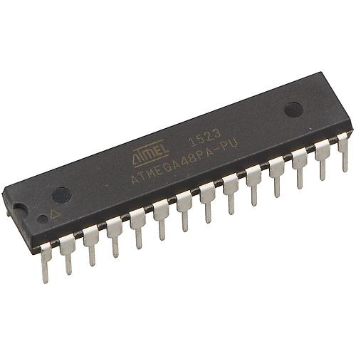
crack atmega48pa mcu fuse bit and readout microprocessor flash memory in the format of binary or heximal
When a change of the logic level (an event) occurs on the Input Capture Pin (ICPn), alternatively on the analog Comparator output (ACO), and this change confirms to the setting of the edge detector, a capture will be triggered.
When a capture is triggered, the 16-bit value of the counter (TCNTn) is written to the Input Capture Register (ICRn). The Input Capture Flag (ICFn) is set at the same system clock as the TCNTn value is copied into ICRn Register.
If enabled (TICIEn = 1), the input capture flag generates an input capture interrupt. The ICFn flag is automatically cleared when the interrupt is executed.
Alternatively the ICFn flag can be cleared by software by writing a logical one to its I/O bit location. Reading the 16-bit value in the Input Capture Register (ICRn) is done by first reading the low byte (ICRnL) and then the high byte (ICRnH).
When the low byte is read the high byte is copied into the high byte Temporary Register (TEMP). When the CPU reads the ICRnH I/O location it will access the TEMP Register.
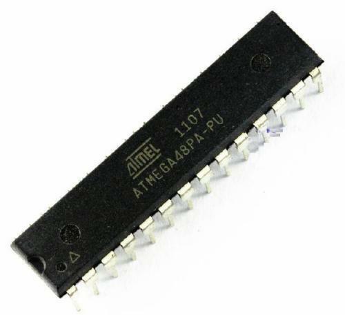
break atmega48pa microcomputer protection
The ICRn Register can only be written when using a Waveform Generation mode that utilizes the ICRn Register for defining the counter’s TOP value. In these cases the Waveform Generation mode (WGMn3:0) bits must be set before the TOP value can be written to the ICRn Register if Reverse engineering MCU atmega324pv Code.
When writing the ICRn Register the high byte must be written to the ICRnH I/O location before the low byte is written to ICRnL. The main trigger source for the input capture unit is the Input Capture Pin (ICPn). Timer/Counter1 can alternatively use the analog comparator output as trigger source for the input capture unit before break microcontroller atmega324a MCU Code.
The Analog Comparator is selected as trigger source by setting the analog Comparator Input Capture (ACIC) bit in the Analog Comparator Control and Status Register (ACSR). Be aware that changing trigger source can trigger a capture;
The input capture flag must therefore be cleared after the change. Both the Input Capture Pin (ICPn) and the Analog Comparator output (ACO) inputs are sampled using the same technique as for the Tn pin. The edge detector is also identical. However, when the noise canceler is enabled, additional logic is inserted before the edge detector, which increases the delay by four system clock cycles. Note that the input of the noise canceler and edge detector is always enabled unless the Timer/Counter is set in a Waveform Generation mode that uses ICRn to define TOP.