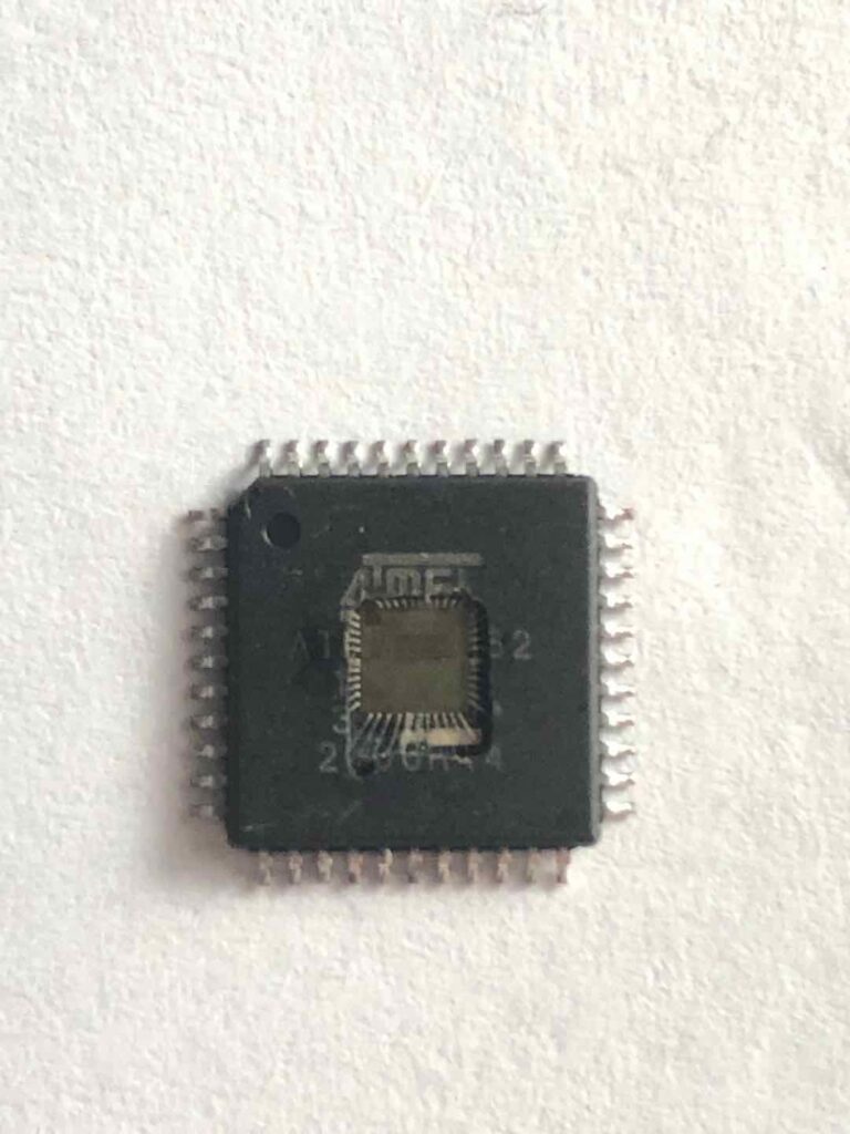
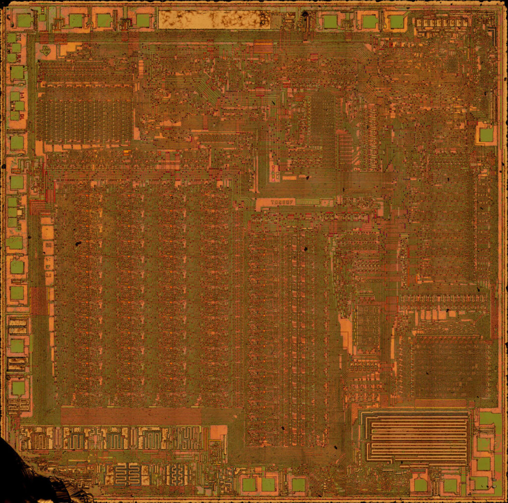
 Reverse Engineering ARM Microcontroller STM32F072R8 Flash Memory
Reverse Engineering ARM Microcontroller STM32F072R8 Flash Memory and readout embedded heximal file from stm32f072rb flash memory after crack microprocessor stm32f072rb locked bit by focus ion beam technique;

The device has the following features:
16 Kbytes of embedded SRAM accessed (read/write) at CPU clock speed with 0 wait states and featuring embedded parity checking with exception generation for fail-critical applications.
The non-volatile memory is divided into two arrays:
64 to 128 Kbytes of embedded Flash memory for programs and data when hack stm32f071vb mcu flash memory protection
Option bytes
The option bytes are used to write-protect the memory (with 4 KB granularity) and/or readout-protect the whole memory with the following options:
Level 0: no readout protection

reverse engineering microcontrollore ARM STM32F072R8 memoria flash e lettura file eshimale incorporato da STM32F072RB memoria flash dopo crack microprocessore STM32F072RB bit bloccato dalla tecnica del fascio ionico di messa a fuoco
Level 1: memory readout protection, the Flash memory cannot be read from or written to if either debug features are connected or boot in RAM is selected by breaking stm32f071rb microcontroller locked bit;
Level 2: chip readout protection, debug features (Arm® Cortex®-M0 serial wire) and boot in RAM selection disabled
At startup, the boot pin and boot selector option bit are used to select one of the three boot options:
boot from User Flash memory
boot from System Memory
boot from embedded SRAM
The boot loader is located in System Memory. It is used to reprogram the Flash memory by using USART on pins PA14/PA15, or PA9/PA10 or I2C on pins PB6/PB7 or through the USB DFU interface.