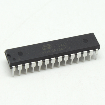
 Recovery Microcontroller ATmega48A Program
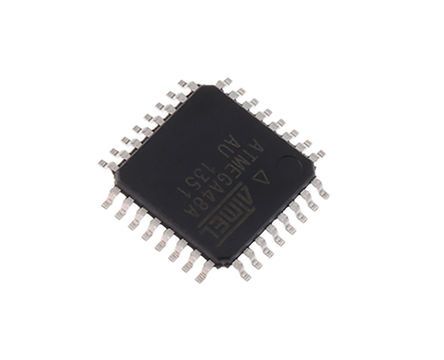
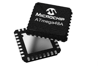
Recovery Microcontroller ATmega48A Program
The Bit Copy instructions BLD (Bit LoaD) and BST (Bit STore) use the T-bit as source or destination for the operated bit. A bit from a register in the Register File can be copied into T by the BST instruction after , and a bit in T can be copied into a bit in a register in the Register File by the BLD instruction.
Bit 5 – H: Half Carry Flag
The Half Carry Flag H indicates a Half Carry in some arithmetic operations. Half Carry Is useful in BCD arithmetic. See the “Instruction Set Description” for detailed information.
Bit 4 – S: Sign Bit, S = N ⊕ V
The S-bit is always an exclusive or between the Negative Flag N and the Two’s Complement Overflow Flag V. See the “Instruction Set Description” for detailed information.
Bit 3 – V: Two’s Complement Overflow Flag
The Two’s Complement Overflow Flag V supports two’s complement arithmetics. See the “Instruction Set Description” for detailed information.
Bit 2 – N: Negative Flag
The Negative Flag N indicates a negative result in an arithmetic or logic operation. See the “Instruction Set Description” for detailed information.
Bit 1 – Z: Zero Flag
The Zero Flag Z indicates a zero result in an arithmetic or logic operation. See the “Instruction Set Description” for detailed information.
Bit 0 – C: Carry Flag
The Carry Flag C indicates a carry in an arithmetic or logic operation. See the “Instruction Set Description” for detailed information.
The Register File is optimized for the AVR Enhanced RISC instruction set in the purpose of Break PIC18F4331 Microprocessor Eeprom Memory. In order to achieve the required performance and flexibility, the following input/output schemes are supported by the Register File:
One 8-bit output operand and one 8-bit result input
Two 8-bit output operands and one 8-bit result input
Two 8-bit output operands and one 16-bit result input
One 16-bit output operand and one 16-bit result input
Figure 5-2 shows the structure of the 32 general purpose working registers in the CPU.
Програма відновлення мікроконтролера ATmega48A передбачає розширені методи злому та декодування зашифрованого та заблокованого мікропрограмного забезпечення, що зберігається в його захищеній флеш-пам’яті та пам’яті EEPROM. Будучи захисним мікроконтролером (MCU), ATmega48A містить надійні функції безпеки для захисту своїх двійкових і шістнадцяткових даних, що робить зворотне проектування необхідним для законних цілей, таких як відновлення функціональності або клонування вбудованого програмного забезпечення.
Most of the instructions operating on the Register File have direct access to all registers, and most of them are single cycle instructions.
Each register is also assigned a data memory address, mapping them directly into the first 32 locations of the user Data Space. Although not being physically implemented as SRAM locations only when Microprocessor PIC18F2515 Heximal File Recovery, this memory organization provides great flexibility in access of the registers, as the X-, Y- and Z-pointer registers can be set to index any register in the file.
The registers R26..R31 have some added functions to their general purpose usage. These registers are 16-bit address pointers for indirect addressing of the data space. The three indirect address registers X, Y, and Z are defined as described in Figure 5-3.
The Stack is mainly used for storing temporary data, for storing local variables and for storing return addresses after interrupts and subroutine calls. The Stack Pointer Register always points to the top of the Stack. Note that the Stack is implemented as growing from higher memory locations to lower memory locations. This implies that a Stack PUSH command decreases the Stack Pointer.
The Stack Pointer points to the data SRAM Stack area where the Subroutine and Interrupt Stacks are located. This Stack space in the data SRAM must be defined by the program before any subroutine calls are executed or interrupts are enabled to provide greater support for Break Microcontroller TI TMS320F28232PGFA Protection. The Stack Pointer must be set to point above 0x0100, preferably RAMEND.
The Stack Pointer is decremented by one when data is pushed onto the Stack with the PUSH instruction, and it is decremented by two when the return address is pushed onto the Stack with subroutine call or interrupt. The Stack Pointer is incremented by one when data is popped from the Stack with the POP instruction, and it is incremented by two when data is popped from the Stack with return from subroutine RET or return from interrupt RETI.
بازیابی میکروکنترلر برنامه ATmega48A شامل روش های پیشرفته ای برای کرک و رمزگشایی سیستم عامل رمزگذاری شده و قفل شده ذخیره شده در حافظه فلش ایمن و حافظه EEPROM است. به عنوان یک میکروکنترلر محافظ (MCU)، ATmega48A دارای ویژگیهای امنیتی قوی برای محافظت از دادههای باینری و هگزیمال خود است، که مهندسی معکوس را برای اهداف قانونی مانند بازیابی عملکرد یا شبیهسازی نرمافزار تعبیهشده ضروری میسازد.
The AVR Stack Pointer is implemented as two 8-bit registers in the I/O space. The number of bits actually used is implementation dependent. Note that the data space in some implementations of the AVR architecture is so small that only SPL is needed when Crack MCU firmware. In this case, the SPH Register will not be present.