 Recover Microprocessor ATmega1281PA Flash
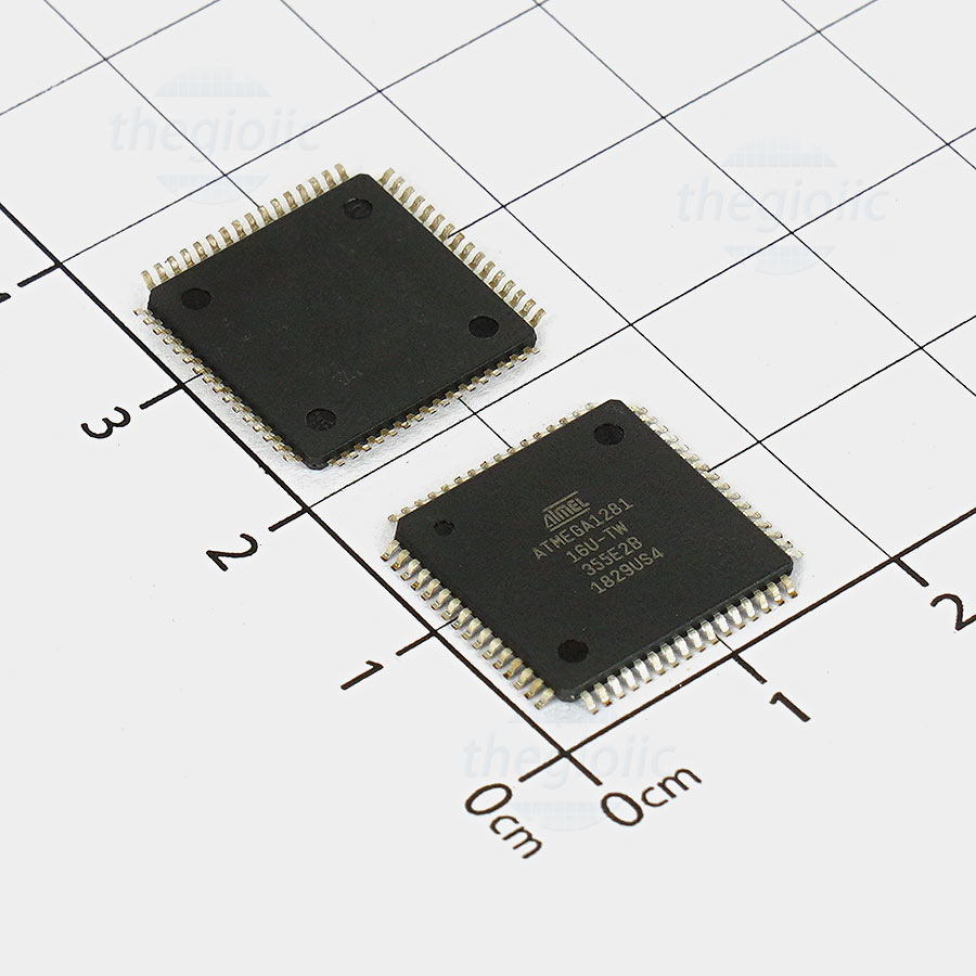
Recover Microprocessor ATmega1281PA Flash heximal file, copy mcu atmega1281pa memory content to new microcontroller and provide the same functions, the security fuse bit of microcontroller atmega1281pa will be cracked reset the status.
The FOCnA/FOCnB/FOCnC bits are only active when the WGMn3:0 bits specifies a non-PWM mode. When writing a logical one to the FOCnA/FOCnB/FOCnC bit, an immediate compare match is forced on the waveform generation unit.
Recover Microprocessor ATmega1281PA Flash heximal file, copy mcu atmega1281pa memory content to new microcontroller and provide the same functions, the security fuse bit of microcontroller atmega1281pa will be cracked reset the status.
The OCnA/OCnB/OCnC output is changed according to its COMnx1:0 bits setting. Note that the FOCnA/FOCnB/FOCnC bits are implemented as strobes. Therefore it is the value present in the COMnx1:0 bits that determine the effect of the forced compare.
A FOCnA/FOCnB/FOCnC strobe will not generate any interrupt nor will it clear the timer in Clear Timer on Compare Match (CTC) mode using OCRnA as TOP before break microcontroller pic16f886.
unlock encrypted mcu atmega1281 microcontroller fuse bit and dump embedded firmware from flash memory and eeprom memory
The two Timer/Counter I/O locations (TCNTnH and TCNTnL, combined TCNTn) give direct access, both for read and for write operations, to the Timer/Counter unit 16-bit counter after Recover MICROPROCESSOR flash.
To ensure that both the high and low bytes are read and written simultaneously when the CPU accesses these registers, the access is performed using an 8-bit temporary High Byte Register (TEMP). This temporary register is shared by all the other 16-bit registers. See “Accessing 16-bit Registers” on page 137.
Modifying the counter (TCNTn) while the counter is running introduces a risk of missing a compare match between TCNTn and one of the OCRnx Registers when attacking dsp mcu texas instrument tms320f2401pg hex.
Writing to the TCNTn Register blocks (removes) the compare match on the following timer clock for all compare units. The Output Compare Registers contain a 16-bit value that is continuously compared with the counter value (TCNTn).
A match can be used to generate an Output Compare interrupt, or to generate a waveform output on the OCnx pin. The Output Compare Registers are 16-bit in size. To ensure that both the high and low bytes are written simultaneously when the CPU writes to these registers, the access is performed using an 8-bit temporary High Byte Register (TEMP).
recover secured microprocessor ATMEGA1281 flash memory and readout mcu embedded firmware from flash program memory and eeprom data memory
This temporary register is shared by all the other 16-bit registers. See “Accessing 16-bit Registers” on page 137. The Input Capture is updated with the counter (TCNTn) value each time an event occurs on the ICPn pin (or optionally on the Analog Comparator output for Timer/Counter1).
The Input Capture can be used for defining the counter TOP value. The Input Capture Register is 16-bit in size. To ensure that both the high and low bytes are read simultaneously when the CPU accesses these registers, the access is performed using an 8-bit temporary High Byte Register (TEMP).
This temporary register is shared by all the other 16-bit registers. See “Accessing 16-bit Registers” on page 137.