 Recover MCU ATmega169PA Code
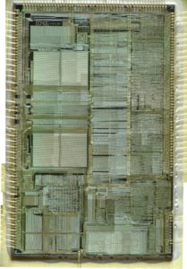
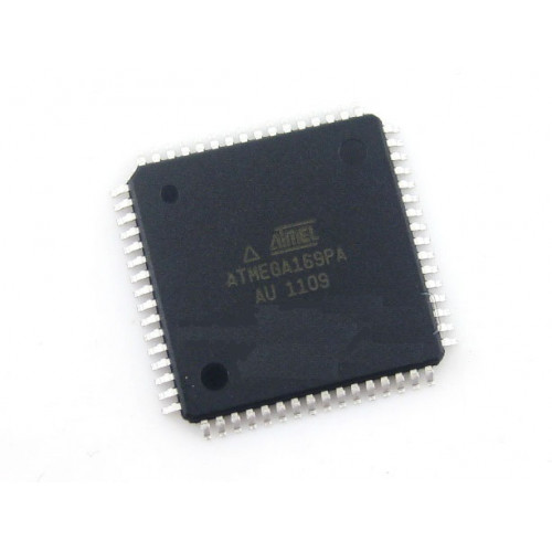
Recover MCU ATmega169PA Code from microcontroller ATmega169PA memory include flash and eeprom storage system, disable tamper resistance system through MCU cracking process and extract code from Microccontroller ATmega169PA;
Recover MCU ATmega169PA Code from microcontroller ATmega169PA memory include flash and eeprom storage system, disable tamper resistance system through MCU cracking process and extract code from Microccontroller ATmega169PA
Using the ICRn Register for defining TOP works well when using fixed TOP values. By using ICRn, the OCRnA Register is free to be used for generating a PWM output on OCnA. However, if the base PWM frequency is actively changed (by changing the TOP value), using the OCRnA as TOP is clearly a better choice due to its double buffer feature.
unlock ATMEGA169PA microprocessor protected and dump firmware code out from flash memory and eeprom memory
In fast PWM mode, the compare units allow generation of PWM waveforms on the OCnx pins. Setting the COMnx1:0 bits to two will produce a non-inverted PWM and an inverted PWM output can be generated by setting the COMnx1:0 to three (see Table on page 158).
The actual OCnx value will only be visible on the port pin if the data direction for the port pin is set as output (DDR_OCnx). The PWM waveform is generated by setting (or clearing) the OCnx Register at the compare match between OCRnx and TCNTn, and clearing (or setting) the OCnx Register at the timer clock cycle the counter is cleared (changes from TOP to BOTTOM).
The PWM frequency for the output can be calculated by the following equation:
The N variable represents the prescaler divider (1, 8, 64, 256, or 1024).
The extreme values for the OCRnx Register represents special cases when generating a PWM waveform output in the fast PWM mode. If the OCRnx is set equal to BOTTOM (0x0000) the output will be a narrow spike for each TOP+1 timer clock cycle. Setting the OCRnx equal to TOP will result in a constant high or low output (depending on the polarity of the output set by the COMnx1:0 bits.) before MCU PIC16F886 firmware copying
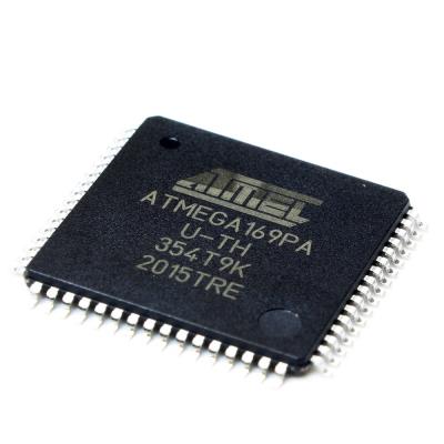
decrypt ATMEGA169pa microcontroller fuse bit and extract heximal program from flash memory
A frequency (with 50% duty cycle) waveform output in fast PWM mode can be achieved by setting OCnA to toggle its logical level on each compare match (COMnA1:0 = 1). This applies only if OCR1A is used to define the TOP value (WGM13:0 = 15). The waveform generated will have a maximum frequency of fOCnA = fclk_I/O/2 when OCRnA is set to zero (0x0000). This feature is similar to the OCnA toggle in CTC mode, except the double buffer feature of the Output Compare unit is enabled in the fast PWM mode when MCU PIC16F72 heximal attacking.