 Recover MCU ATmega1281V Binary
The ATmega1281V microcontroller is a low-voltage, highly specialized 8-bit AVR RISC processor that serves as the silent muscle behind crucial hardware platforms. It is extensively deployed in portable medical diagnostic tools, remote battery-powered environmental dataloggers, smart metering infrastructure, and localized industrial automation networks. What makes this chip uniquely suited for these industries is its combination of ultra-low power consumption and high-capacity integration—featuring 128 KB of in-system self-programmable flash, 4 KB of persistent eeprom memory, and advanced power-save modes that maximize field longevity. The core intellectual property driving these specialized functions is stored inside the chip as an embedded program. However, manufacturing firms often run into severe operational gridlock when a critical field unit fails or requires an update, yet the original design file, source code, or historical data archive has completely vanished. When standard recovery methods fail, our elite engineering facility steps in to provide a secure path to recover mcu atmega1281v binary data, restoring full access to your legacy hardware logic.
The ATmega1281 is a low-power CMOS 8-bit microcontroller based on the AVR enhanced RISC architecture. By executing powerful instructions in a single clock cycle, the ATmega1281v achieves throughputs approaching 1 MIPS per MHz allowing the system designer to optimize power consumption versus processing speed.
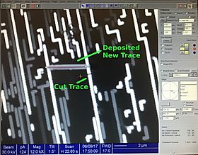
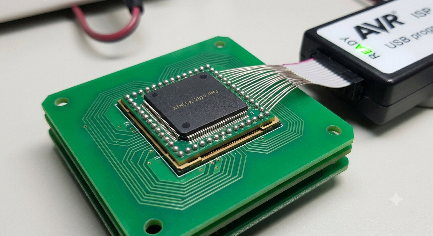
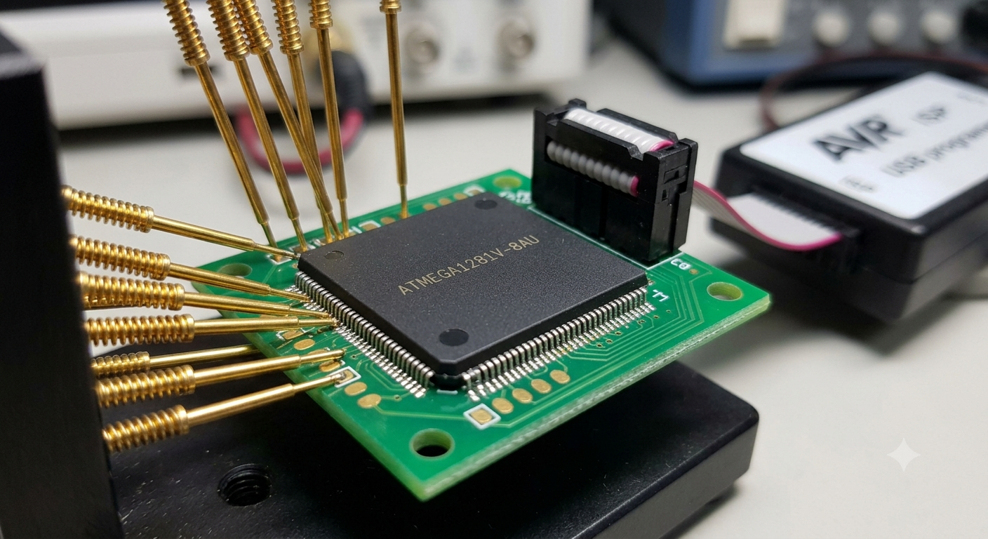
Accessing machine code inside a protected or locked integrated circuit requires navigating dense physical defense systems designed intentionally to prevent unauthorized reading. To systematically attack, break, and decode these internal security configurations, our specialized micro-electronics laboratory applies highly controlled chemical and electrical processes. Technicians first decapsulate the outer protective packaging of the component using precision acid application to lay bare the delicate silicon micro-die. Under high-powered magnification, our engineers can carefully locate the physical registers housing the protective code fuses. By applying targeted voltage glitching, localized laser manipulation, or precise micro-probing to the silicon substrate, we can temporarily bypass the embedded security bits without causing any physical degradation to the hardware. This targeted intervention allows us to smoothly read out the tightly guarded firmware, raw data, and application profiles directly from the internal flash sectors. The definitive deliverable from this delicate engineering operation is a clean, completely uncorrupted heximal file that perfectly mirrors the instructions of your original system.
Tescilli kontrol kodunuz eski flash bloklarında, dahili EEPROM alanlarında veya çevresel PLD matrislerinde bulunuyor olsun, özel okuma araçlarımız Microchip ATMEGA1281V mikroişlemcisinden tüm verileri güvenli şekilde elde eder.
Ekibimiz ham program dosyasını başarıyla geri kazandıktan sonra, geliştiricileriniz tüm mantıksal yapıyı modern ve kolay temin edilebilen bir Microchip ATMEGA1281V mikrodenetleyicisine aktarma yeteneği kazanır.
Bu kapsamlı geri kazanım süreci, eski nesil Microchip ATMEGA1281V mikroişlemcilerinin aynı operasyonel profillerini yeniden oluşturmayı ve tamamen yeni bir yazılım yedeği oluşturmayı kolaylaştırır.
The AVR core combines a rich instruction set with 32 general purpose working registers. All the 32 registers are directly connected to the Arithmetic Logic Unit (ALU), allowing two independent registers to be accessed in one single instruction executed in one clock cycle. The resulting architecture is more code efficient while achieving throughputs up to ten times faster than conventional CISC microcontrollers. The ATmega1281v provides the following features: 64K/128K/256K bytes of In-System Programmable Flash with Read-While-Write capabilities, 4K bytes EEPROM, 8K bytes SRAM, 54/86 general purpose I/O lines, 32 general purpose working registers.
Niezależnie od tego, czy własnościowy kod sterowania znajduje się w starszych blokach pamięci Flash, wewnętrznych sektorach EEPROM czy peryferyjnych macierzach PLD, nasze dedykowane narzędzia odczytu bezpiecznie pobierają wszystkie dane z mikroprocesora Microchip ATMEGA1281V.
Po pomyślnym odzyskaniu surowego pliku programu programiści uzyskują możliwość przeniesienia całej struktury logicznej na nowoczesny i łatwo dostępny mikrokontroler Microchip ATMEGA1281V.
Ten kompleksowy proces odzyskiwania pozwala wiernie odtworzyć profile działania starszych mikroprocesorów Microchip ATMEGA1281V oraz utworzyć całkowicie nową kopię zapasową oprogramowania.
Real Time Counter (RTC), six flexible Timer/Counters with compare modes and PWM, 4 USARTs, a byte oriented 2-wire Serial Interface, a 16-channel, 10-bit ADC with optional differential input stage with programmable gain, programmable Watchdog Timer with Internal Oscillator, an SPI serial port, IEEE std. 1149.1 compliant JTAG test interface.
Also used for accessing the On-MCU Debug system and programming and six software selectable power saving modes. The Idle mode stops the CPU while allowing the SRAM, Timer/Counters, SPI port, and interrupt system to continue functioning. The Power-down mode saves the register contents but freezes the Oscillator, disabling all other MCU functions until the next interrupt or Hardware Reset. In Power-save mode, the asynchronous timer continues to run, allowing the user to maintain a timer base while the rest of the device is sleeping. The ADC Noise Reduction mode stops the CPU and all I/O modules except Asynchronous Timer and ADC, to minimize switching noise during ADC conversions. In Standby mode, the Crystal/Resonator Oscillator is running while the rest of the device is sleeping. This allows very fast start-up combined with low power consumption. In Extended Standby mode, both the main Oscillator and the Asynchronous Timer continue to run.
Незалежно від того, чи знаходиться ваш власний керуючий код у старих блоках Flash, внутрішніх секторах EEPROM або периферійних матрицях PLD, наші спеціалізовані інструменти безпечно отримують кожен байт інформації з мікропроцесора Microchip ATMEGA1281V.
Після успішного відновлення початкового програмного файлу ваші розробники отримують можливість перенести всю логічну структуру на сучасний і доступний мікроконтролер Microchip ATMEGA1281V.
Такий комплексний процес відновлення дозволяє точно відтворити робочі профілі застарілих мікропроцесорів Microchip ATMEGA1281V та сформувати повністю нову резервну копію програмного забезпечення.
The fundamental purpose of choosing to hack, duplicate, or extract software from a secured microcontroller layout is to eliminate single-point supply chain failures and secure long-term technical autonomy. When an active system archive is completely severed, engineers utilize our advanced recovery solutions to extract the vital firmware instructions before a full-scale, incredibly expensive system redesign is forced upon your engineering budget. Whether your proprietary control code is isolated inside older flash blocks, internal eeprom sectors, or peripheral PLD matrices, our custom reading tools pull every byte of information safely. Once our team successfully retrieves the raw program file, your developers gain the immediate capability to clone the entire logic structure onto a modern, readily available replacement microcontroller. This comprehensive recovery ensures you can easily duplicate the exact operational profiles of legacy components, compile an entirely fresh software backup, and confidently manufacture drop-in replacements, making sure your active production lines keep moving forward without experiencing unexpected field downtime.
Ať už je proprietární řídicí kód uložen ve starších blocích Flash, interních sektorech EEPROM nebo periferních maticích PLD, naše specializované nástroje bezpečně získají každý bajt dat z mikroprocesoru Microchip ATMEGA1281V.
Po úspěšném obnovení původního programového souboru získají vývojáři možnost přenést kompletní logickou strukturu na moderní a snadno dostupný náhradní mikrokontrolér Microchip ATMEGA1281V.
Tento komplexní proces obnovy umožňuje přesně reprodukovat provozní profily starších mikroprocesorů Microchip ATMEGA1281V a vytvořit zcela novou zálohu softwaru.
Partnering with an experienced technical team to unlock and recover embedded system software delivers massive financial, operational, and strategic benefits to project managers, maintenance engineers, and hardware developers alike. Instead of exhausting immense corporate capital and spending quarters of valuable engineering time trying to reverse-engineer and re-write complex encrypted software architectures from scratch—a risky process that notoriously introduces hidden bugs—our advanced extraction pipeline delivers a fast, precise path to a fully verified binary file. This complete structural continuity ensures that every newly generated duplicate circuit board matches the exact performance and behavioral profile of the field-tested units your clients already trust. By utilizing our specialized microcontroller recovery solutions, your enterprise effectively mitigates the existential threats of part obsolescence, safeguards vital corporate intellectual property, and secures a fully predictable, stable roadmap for your industrial hardware investments for many years to come.
Независимо дали вашият собствен управляващ код се намира в по-стари Flash блокове, вътрешни EEPROM сектори или периферни PLD матрици, нашите специализирани инструменти безопасно извличат всеки байт информация от микропроцесора Microchip ATMEGA1281V.
След като нашият екип успешно възстанови първичния програмен файл, вашите разработчици получават възможност незабавно да прехвърлят цялата логическа структура върху съвременен и лесно достъпен заместващ микроконтролер Microchip ATMEGA1281V.
Този цялостен процес на възстановяване гарантира възможността за точно възпроизвеждане на работните профили на по-старите микропроцесори Microchip ATMEGA1281V и създаване на напълно ново резервно копие на софтуера.