Copy Chip PIC16F777 Firmware
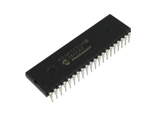
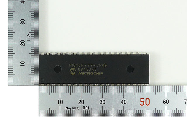
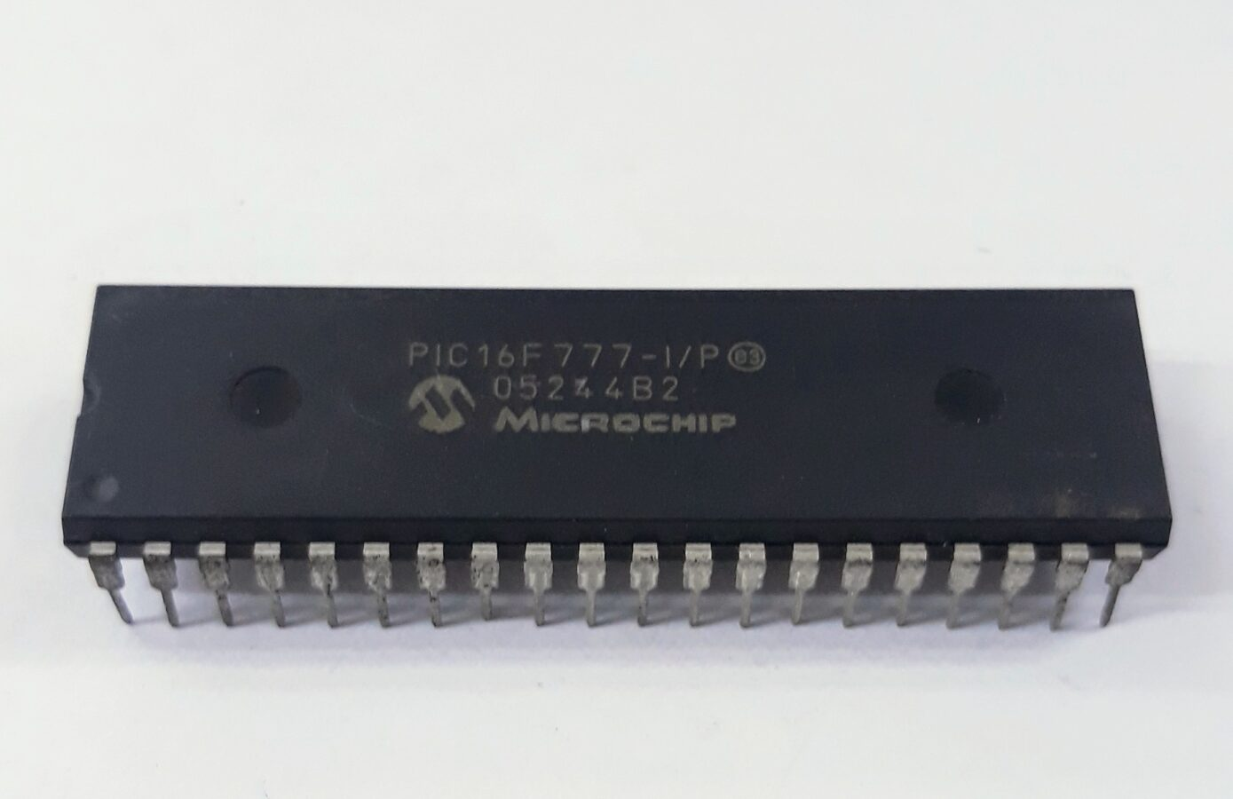
The PIC16F777 is a powerhouse in the 8-bit embedded landscape, frequently selected for its high pin count and advanced peripheral set, including three PWM modules and a 10-bit Analog-to-Digital converter. This versatile MCU is a critical component in complex systems such as industrial power inverters, sophisticated laboratory equipment, and advanced automotive diagnostics tools. Its unique features—like the nanoWatt technology for extreme power efficiency and a large flash memory array—allow it to execute intricate program logic while maintaining a low thermal footprint. However, in most commercial deployments, these devices are shipped in a locked state, utilizing protective security fuses to ensure the internal binary remains secured. For many industries, the inability to access this protected logic during a hardware failure or when the original source code is unavailable can lead to costly downtime and the threat of total system obsolescence.
Our specialized laboratory provides a high-fidelity solution to break through these hardware-level restrictions and retrieve the essential heximal data required for system continuity. To successfully attack a secured MCU, our technical team may perform a delicate procedure to decapsulate the silicon chip, exposing the internal memory structure for direct micro-probing. This physical approach enables us to decode the protected logic and extract the firmware directly from the flash or eeprom segments without damaging the core functionality. Whether you need to clone an obsolete controller for emergency backup or duplicate the program from an encrypted chip to safeguard your production line, our process ensures a perfect extraction of the binary archive. By choosing to hack the physical and logical barriers of the PIC16F777, we turn a secured “black box” back into a manageable and portable file for your engineering team.
Status Register:
The Status register contains the arithmetic status of the ALU, the Reset status and the bank select bits for data memory, The Status register can be the destination for any instruction, as with any other register. If the Status register is the destination for an instruction that affects the Z, DC or C bits, then the write to these three bits is disabled. These bits are set or cleared according to the device logic. Furthermore, the TO and PD bits are not writable, therefore, the result of an instruction with the Status register as destination may be different than intended. For example, CLRF STATUS, will clear the upper three bits and set the Z bit. This leaves the Status register as 000u u1uu (where u = unchanged). It is recommended, therefore, that only BCF, BSF, SWAPF and MOVWF instructions are used to alter the Status register because these instructions do not affect the Z, C or DC bits from the Status register. For other instructions not affecting any Status bits e, the result of an instruction with the Status register as destination may be different than intended.
The Program Counter (PC) is 13 bits wide. The low byte comes from the PCL register which is a readable and writable register. The upper bits (PC<12:8>) are not readable but are indirectly writable through the PCLATH register. On any Reset, the upper bits of the PC will be cleared. Figure 2-4 shows the two situations for the loading of the PC. The upper example in the figure shows how the PC is loaded on a write to PCL (PCLATH<4:0> → PCH). The lower example in the figure shows how the PC is loaded during a CALL or GOTO instruction (PCLATH<4:3> → PCH). The stack operates as a circular buffer. This means that after the stack has been PUSHed eight times, the ninth push overwrites the value that was stored from the first push. The tenth push overwrites the second push (and so on). PIC16F7X7 devices are capable of addressing a con- been PUSHed eight times, the ninth push overwrites the value that was stored from the first push. The tenth push overwrites the second push (and so on). tinuous 8K word block of program memory. The CALL and GOTO instructions provide only 11 bits of address to allow branching within any 2K program memory page. When doing a CALL or GOTO instruction, the upper 2 bits of the address are provided by PCLATH<4:3>.
The fundamental purpose of performing a targeted attack to break the security of a protected PIC16F777 is to protect decades of investment in specialized machinery and industrial assets. For many end users, the ability to retrieve a heximal archive from a locked MCU is the only viable path to clone or duplicate essential components when the original vendor no longer provides support. By deciding to decode or hack the secured architecture of an existing chip, organizations can successfully duplicate their vital firmware onto fresh hardware, effectively bypassing the constraints of a locked or encrypted environment. Our expertise allows you to duplicate the flash and eeprom data from any embedded controller, ensuring that the binary logic is preserved with 100% accuracy. This ensures that the program remains a functional asset, preventing the catastrophic loss of proprietary algorithms stored within the memory.
Ultimately, our recovery service provides the end user with total autonomy over their hardware maintenance and software lifecycle. Instead of facing the daunting task of rewriting complex source code from scratch, you can simply retrieve the heximal file and clone the locked program directly onto a replacement MCU. We specialize in the surgical precision required to decapsulate and attack these high-security components, ensuring that the binary data is handled with the highest level of integrity. By providing a reliable way to decode and duplicate the firmware of a secured PIC16F777, we turn a protected archive into a functional reality once again. Our commitment is to ensure that your data, memory, and program files remain accessible, regardless of the protective measures originally placed upon the silicon, guaranteeing that your critical infrastructure stays operational well into the future.