 Break Microcontroller PIC24FJ16GA002 Heximal
Break Microcontroller PIC24FJ16GA002 program memory and data memory, readout heximal from MCU PIC24FJ16GA002 for microprocessor cloning.
Break Microcontroller PIC24FJ16GA002 program memory and data memory, readout heximal from MCU PIC24FJ16GA002 for microprocessor cloning
The mode of operation, i.e., the behavior of the Timer/Counter and the Output Compare pins, is defined by the combination of the Waveform Generation mode (WGM02:0) and Compare Output mode (COM0x1:0) bits.
The Compare Output mode bits do not affect the counting sequence, while the Waveform Generation mode bits do. The COM0x1:0 bits control whether the PWM output generated should be inverted or not (inverted or non-inverted PWM) if break microcontroller ATmega1284 memory.

unlock PIC24FJ16GA002 microcontroller fuse bit and clone heximal program from flash memory
For non-PWM modes the COM0x1:0 bits control whether the output should be set, cleared, or toggled at a Compare Match (See “Compare Match Output Unit” on page 146.).For detailed timing information see “Timer/Counter Timing Diagrams”.
The simplest mode of operation is the Normal mode (WGM02:0 = 0). In this mode the counting direction is always up (incrementing), and no counter clear is performed. The counter simply overruns when it passes its maximum 8-bit value (TOP = 0xFF) and then restarts from the bottom (0x00) when microcontroller ATmega1284V memory reverse engineering.
In normal operation the Timer/Counter Overflow Flag (TOV0) will be set in the same timer clock cycle as the TCNT0 becomes zero. The TOV0 Flag in this case behaves like a ninth bit, except that it is only set, not cleared.
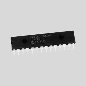
attack PIC24FJ16GA002 mcu protection and restore flash memory program and data file
However, combined with the timer overflow interrupt that automatically clears the TOV0 Flag, the timer resolution can be increased by software. There are no special cases to consider in the Normal mode, a new counter value can be written anytime. The Output Compare Unit can be used to generate interrupts at some given time.
Using the Output Compare to generate waveforms in Normal mode is not recommended, since this will occupy too much of the CPU time.