 Break MCU PIC16F876 Flash
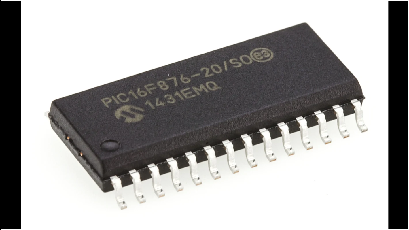
Breaking MCU PIC16F876 flash involves cracking the encrypted and secured firmware stored in its flash memory and EEPROM memory. This secured PIC16F876 microcontroller unit (MCU) is often used in embedded systems, where its firmware and software are protected to prevent unauthorized access. When attempting to break the protection, reverse engineering techniques are typically employed to decode or decrypt the encrypted PIC16F876 microprocessor’s locked binary and heximal data within the flash memory.
break MCU PIC16F876 lampu kilat melu retak perangkat kukuh ndhelik lan aman disimpen ing memori lampu kilat lan memori EEPROM. Unit mikrokontroler (MCU) PIC16F876 sing aman iki asring digunakake ing sistem sing dipasang, ing ngendi perangkat kukuh lan piranti lunak dilindhungi kanggo nyegah akses sing ora sah. Nalika nyoba ngrusak proteksi, teknik reverse engineering biasane digunakake kanggo decode utawa dekripsi data biner lan heksimal mikroprosesor PIC16F876 sing dikunci ing memori lampu kilat.
The process begins with analyzing the microprocessor’s architecture to identify and bypass the encryption protocols securing the firmware. Specialized tools are used to attack the encryption and unlock the flash memory, allowing access to the embedded program and source code. Once the protective measures are defeated, the firmware can be restored, cloned, or replicated for system diagnostics, repair, or further development.
Unlocking the PIC16F876 MCU’s flash memory allows for the recovery of critical software, which is particularly useful in situations where the original source code is lost, corrupted, or unavailable. Cloning the firmware ensures that the program can be duplicated for use in similar systems or to create backups for future use.
MCU PIC16F876 ఫ్లాష్ను విచ్ఛిన్నం చేయడంలో దాని ఫ్లాష్ మెమరీ మరియు EEPROM మెమరీలో నిల్వ చేయబడిన ఎన్క్రిప్టెడ్ మరియు సురక్షిత ఫర్మ్వేర్ను క్రాక్ చేయడం ఉంటుంది. ఈ సురక్షిత PIC16F876 మైక్రోకంట్రోలర్ యూనిట్ (MCU) తరచుగా ఎంబెడెడ్ సిస్టమ్లలో ఉపయోగించబడుతుంది, ఇక్కడ అనధికార ప్రాప్యతను నిరోధించడానికి దాని ఫర్మ్వేర్ మరియు సాఫ్ట్వేర్ రక్షించబడతాయి. రక్షణను విచ్ఛిన్నం చేయడానికి ప్రయత్నించినప్పుడు, ఫ్లాష్ మెమరీలో గుప్తీకరించిన PIC16F876 మైక్రోప్రాసెసర్ యొక్క లాక్ చేయబడిన బైనరీ మరియు హెక్సిమల్ డేటాను డీకోడ్ చేయడానికి లేదా డీక్రిప్ట్ చేయడానికి రివర్స్ ఇంజనీరింగ్ పద్ధతులు సాధారణంగా ఉపయోగించబడతాయి.
However, it is crucial to note that breaking the protection of an MCU like the PIC16F876 should be done within legal and ethical boundaries. Unauthorized decryption or cloning of the firmware could lead to intellectual property violations and legal consequences. As such, this process should be carried out responsibly, ensuring the preservation of both the software’s integrity and the rights of the original creators.
The STATUS register contains the arithmetic status of the ALU, the RESET status and the bank select bits for data memory. The STATUS register can be the destination for any instruction, as with any other register. If the STATUS register is the destination for an instruction that affects the Z, DC or C bits, then the write to these three bits is disabled.
These bits are set or cleared according to the device logic. Furthermore, the TO and PD bits are not writable, therefore, the result of an instruction with the STATUS register as destination may be different than intended for the purpose of Break IC SST89E58RD2A Software.
Break Mcu PIC16F876 Flash
For example, CLRF STATUS will clear the upper three bits and set the Z bit. This leaves the STATUS register as 000u u1uu (where u = unchanged). It is recommended, therefore, that only BCF, BSF, SWAPF and MOVWF instructions are used to alter the STATUS register, because these instructions do not affect the Z, C or DC bits from the STATUS register.
For other instructions not affecting any status bits, see the “Instruction Set Summary.”
The OPTION_REG Register is a breakable and writable register, which contains various control bits to configure the TMR0 prescaler/WDT postscaler (single assignable register known also as the prescaler), the External INT Interrupt, TMR0 and the weak pull-ups on PORTB.
Um den Flash-Speicher des MCU PIC16F876 zu knacken, muss die verschlüsselte und gesicherte Firmware geknackt werden, die in seinem Flash-Speicher und EEPROM-Speicher gespeichert ist. Diese gesicherte Mikrocontrollereinheit (MCU) PIC16F876 wird häufig in eingebetteten Systemen verwendet, in denen die Firmware und Software vor unbefugtem Zugriff geschützt sind. Beim Versuch, den Schutz zu knacken, werden normalerweise Reverse-Engineering-Techniken eingesetzt, um die gesperrten binären und hexadezimalen Daten des verschlüsselten Mikroprozessors PIC16F876 im Flash-Speicher zu dekodieren oder zu entschlüsseln.
The program counter (PC) is 13-bits wide. The low byte comes from the PCL register, which is a breakable and writable register. The upper bits (PC<12:8>) are not breakable, but are indirectly writable through the PCLATH register to facilitate the process of Recover MCU DSPIC30F6013A30IP Firmware. On any RESET, the upper bits of the PC will be cleared. Figure 2-5 shows the two situations for the loading of the PC.
The upper example in the figure shows how the PC is loaded on a write to PCL (PCLATH<4:0> → PCH). The lower example in the figure shows how the PC is loaded during aCALL orGOTO instruction (PCLATH<4:3> → PCH). All PIC16F87X devices are capable of addressing a continuous 8K word block of program memory which is critical for Microcontroller Unlocking.
Break IC PIC16F876 Flash
The CALL and GOTO instructions provide only 11 bits of address to allow branching within any 2K program memory page. When doing aCALL or GOTO instruction, the upper 2 bits of the address are provided by PCLATH<4:3>. When doing a CALL or GOTO instruction, the user must ensure that the page select bits are programmed so that the desired program memory page is addressed before Break Mcu PIC16F876 Flash
If a return from a CALL instruction (or interrupt) is executed, the entire 13-bit PC is popped off the stack. Therefore, manipulation of the PCLATH<4:3> bits is not required for the return instructions (which POPs the address from the stack).