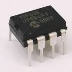
 Break IC PIC12F636 Code
Break IC PIC12F636 Code
it is also critical to know the peripheral features of PIC12F636 i the process of Break IC PIC12F636 Code:
Peripheral Features:
· 6/12 I/O pins with individual direction control:
– High-current source/sink for direct LED drive
– Interrupt-on-pin change
– Individually programmable weak pull-ups/pull-downs
– Ultra Low-Power Wake-up
· Analog comparator module with:
– Up to two analog comparators
– Programmable on-chip voltage reference (CVREF) module (% of VDD)
– Comparator inputs and outputs externally accessible
· Timer0: 8-bit timer/counter with 8-bit programmable prescaler
· Enhanced Timer1:
– 16-bit timer/counter with prescaler
– External Gate Input mode
– Option to use OSC1 and OSC2 in LP mode as Timer1 oscillator if INTOSC mode selected
· KEELOQ® compatible hardware Cryptographic module
· In-Circuit Serial ProgrammingTM (ICSPTM) via two pins
Low Frequency Analog Front-End Features (PIC16F639 only)
· Three input pins for 125 kHz LF input signals
· High input detection sensitivity (3 mVPP, typical)
· Demodulated data, Carrier clock or RSSI output selection
· Input carrier frequency: 125 kHz, typical
· Input modulation frequency: 4 kHz, maximum
· 8 internal configuration registers
· Bidirectional transponder communication (LF talk back)
· Programmable antenna tuning capacitance (up to 63 pF, 1 pF/step)
· Low standby current: 5 ìA (with 3 channels enabled), typical
· Low operating current: 15 ìA (with 3 channels enabled), typical
· Serial Peripheral Interface (SPI™) with internal MCU and external devices
· Supports Battery Back-up mode and batteryless operation with external circuits ly LOQ® compatible hardware Cryptographic module
· In-Circuit Serial ProgrammingTM (ICSPTM) IC breakion;
DEVICE OVERVIEW
This document contains device specific information for the PIC12F635/PIC16F636/639 devices. Additional information may be found in the “PICmicro® Mid-Range MCU Family Reference Manual” (DS33023), which may be obtained from your local Microchip Sales Representative or downloaded from the Microchip web site. The reference manual should be considered a complementary document to this data sheet and is highly recommended reading for a better understanding of the device architecture and operation of the peripheral modules for the purpose of CLONE IC.
