 Break IC ATmega128V Heximal
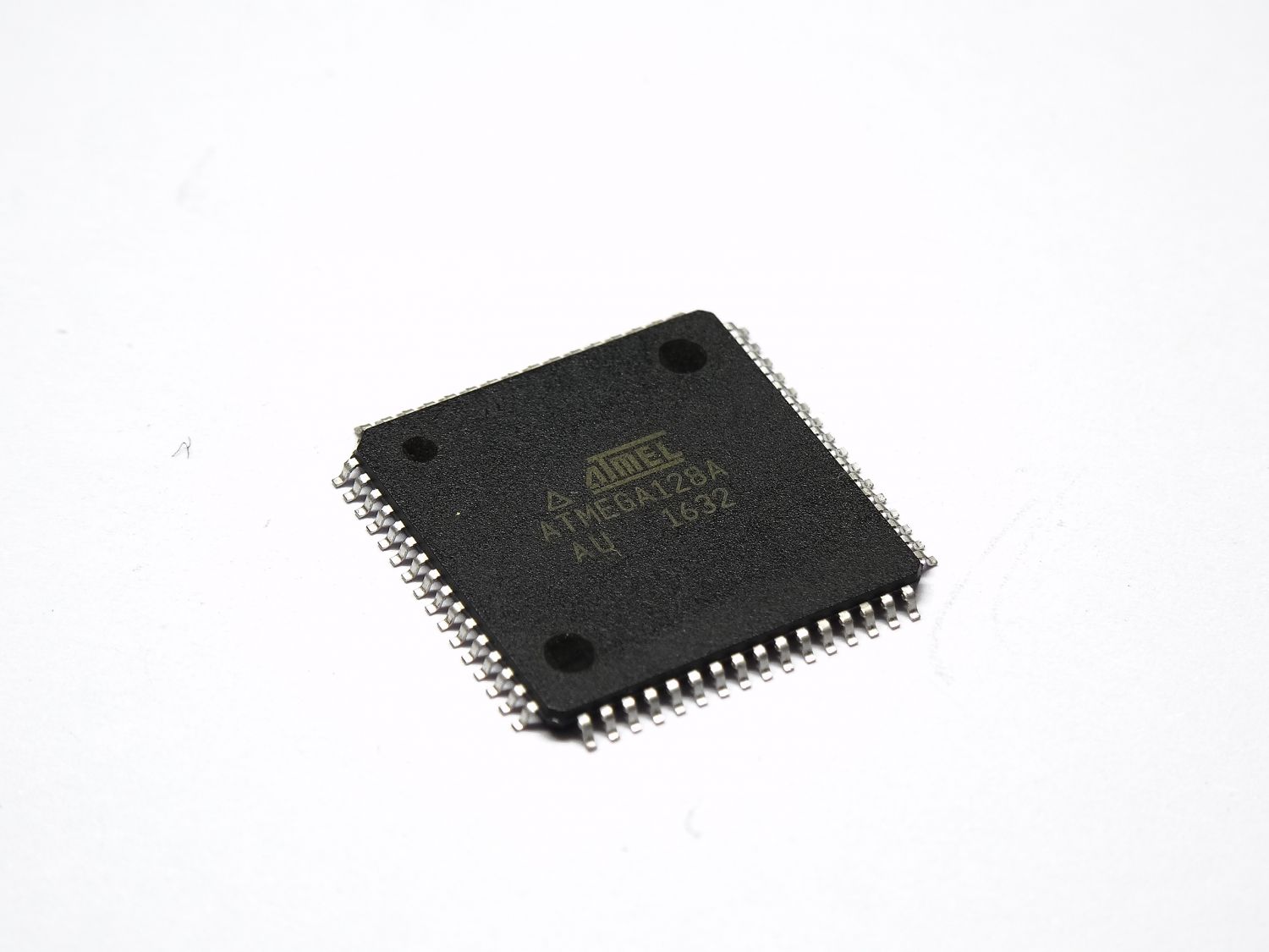
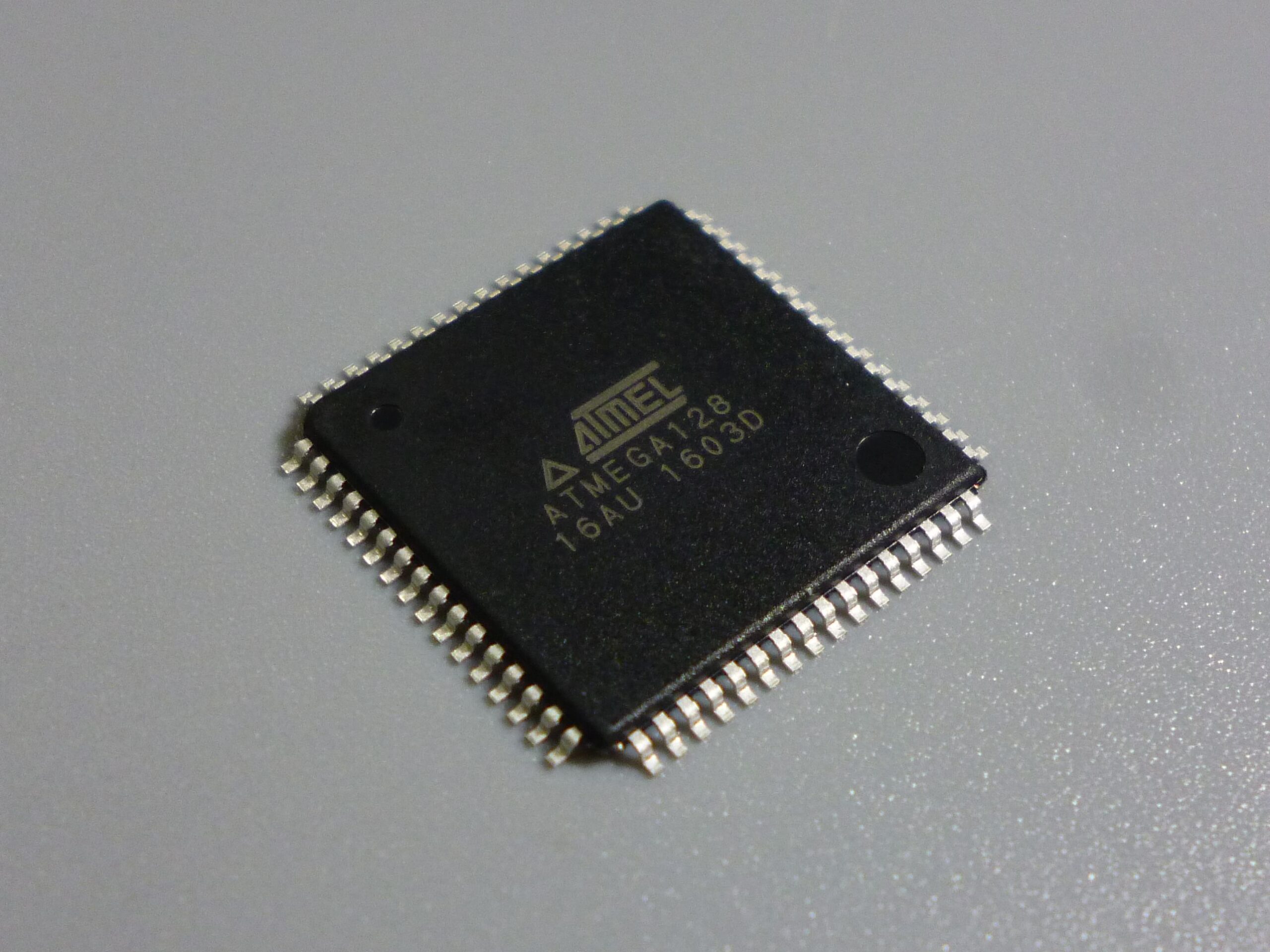
Break IC ATmega128V memory and extract heximal from MCU flash and eeprom memory, unlock microcontroller atmega128v protection set up by the designer and manufacturer;
Break IC ATmega128V memory and extract heximal from MCU flash and eeprom memory, unlock microcontroller atmega128v protection set up by the designer and manufacturer
The general I/O port function is overridde by the Output Compare (OCnx) from the Waveform Generator if either of the COMnx1:0 bits are set. However, the OCnx pin direction (input or output) is still controlled by the Data Direction Register (DDR) for the port pin when copy IC atmega8l heximal.
The Data Direction Register bit for the OCnx pin (DDR_OCnx) must be set as output before the OCnx value is visible on the pin. The port override function is generally independent of the Waveform Generation mode, but there are some exceptions if recover IC STM32F107RCT6 code.
The design of the Output Compare pin logic allows initialization of the OCnx state before the output is enabled. Note that some COMnx1:0 bit settings are reserved for certain modes of operation.
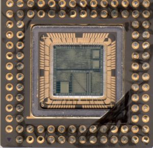
crack secured mcu atmega128v fuse bit and extract firmware program from flash memory
The Waveform Generator uses the COMnx1:0 bits differently in normal, CTC, and PWM modes. For all modes, setting the COMnx1:0 = 0 tells the Waveform Generator that no action on the OCnx Register is to be performed on the next compare match when copy microcontroller pic16f684 firmware.
A change of the COMnx1:0 bits state will have effect at the first compare match after the bits are written. For non-PWM modes, the action can be forced to have immediate effect by using the FOCnx strobe bits.
The mode of operation, i.e., the behavior of the Timer/Counter and the Output Compare pins, is defined by the combination of the Waveform Generation mode (WGMn3:0) and Compare Output mode (COMnx1:0) bits.
unlock ATMEGA128V microcontroller flash memory program
The Compare Output mode bits do not affect the counting sequence, while the Waveform Generation mode bits do. The COMnx1:0 bits control whether the PWM output generated should be inverted or not (inverted or non-inverted PWM). For non-PWM modes the COMnx1:0 bits control whether the output should be set, cleared or toggle at a compare match.