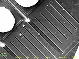
 Break Encrypted IC PIC16F76 Eeprom
Break Encrypted IC PIC16F76 Eeprom and flash memory, extract code from MCU PIC16F76 and copy firmware to new Microcontroller which will provide the same functions as original master processor;

Each PIC12C5XX instruction is a 12-bit word divided into an OPEEPROM, which specifies the instruction type, and one or more operands which further specify the operation of the instruction.
The PIC12C5XX instruction set summary in Table 9-2 groups the instructions into byte-oriented, bit-oriented, and literal and control operations. Table 9-1 shows the opeeprom field descriptions if recover pic16c505 encrypted Eeprom.
For byte-oriented instructions, ’f’ represents a file register designator and ’d’ represents a destination designator. The file register designator is used to specify which one of the 32 file registers is to be used by the instruction.
The destination designator specifies where the result of the operation is to be placed. If ’d’ is ’0’, the result is placed in the W register. If ’d’ is ’1’, the result is placed in the file register specified in the instruction.
Byte-oriented file register operations
For bit-oriented instructions, ’b’ represents a bit field designator which selects the number of the bit affected by the operation, while ’f’ represents the number of the file in which the bit is located when clone microcontroller pic16c54 heximal.
For literal and control operations, ’k’ represents an 8 or 9-bit constant or literal value.
All instructions are executed within a single instruction cycle, unless a conditional test is true or the program counter is changed as a result of an instruction.
In this case, the execution takes two instruction cycles. One instruction cycle consists of four oscillator periods. Thus, for an oscillator frequency of 4 MHz, the normal instruction execution time is 1 µs.
If a conditional test is true or the program counter is changed as a result of an instruction, the instruction execution time is 2 µs. Figure 9-1 shows the three general formats that the instructions can have. All examples in the figure use the following format to represent a hexadecimal number.